1. Introduction
AXIS is a graphical front-end for EMC2 which features a live preview and backplot. It is written in Python and uses Tk and OpenGL to display its user interface.

2. Getting Started
To select AXIS as the front-end for EMC2, edit the .ini file. In the section [DISPLAY] change the DISPLAY line to read
DISPLAY = axis
Then, start EMC2 and select that ini file. The sample configuration sim/axis.ini is already configured to use AXIS as its front-end.
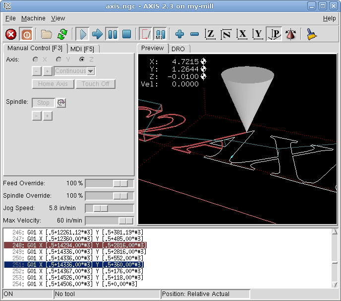
When you start AXIS, a window like the one in Figure [cap:AXIS-Window] is shown.
2.1. A Typical Session
-
Start EMC.
-
Clear the E-STOP (F1) and turn the Machine Power (F2) on.
-
Home all axes.
-
Load the g-code file.
-
Use the preview plot to verify that the program is correct.
-
Set the proper offsets for each axis by jogging and using the Touch Off button.
-
Run the program.
-
To run the same file again, return to step 6. To run a different file, return to step 4. When you’re done, exit AXIS.
3. AXIS Display
The AXIS window contains the following elements:
-
A display area that shows a preview of the loaded file (in this case, "axis.ngc"), as well as the current location of the CNC machine’s "controlled point". Later, this area will display the path the CNC machine has moved through, called the "backplot"
-
A menu bar and toolbar that allow you to perform various actions
-
"Manual Control Tab" , which allows you to make the machine move, turn the spindle on or off, and turn the coolant on or off if included in the ini file.
-
"MDI Tab” , where G-code programs can be entered manually, one line at a time. This also shows the "Active G Codes" which shows which modal G Codes are in effect.
-
"Feed Override" , which allows you to increase or decrease the speed at which EMC executes Feed Moves the selected program. The default maximum is 120% and can be set to a different value in the ini file. See the Integrators Manual for more information on this setting.
-
"Spindle Override" , which allows you to increase or decrease the speed at which EMC commands the spindle to run if spindle control is configured.
-
"Jog Speed" , which allows you to set the jog speed within the limits set in the ini file. See the Integrators Manual for more information on the ini file.
-
"Max Velocity", which allows you to set the maximum velocity for rapids and cap feed rates (except spindle synchronized motion) for dry runs. Currently only AXIS and Halui allow you to set it.
-
A text display area that shows the G-code source of the loaded file.
-
A status bar which shows the state of the machine. In this screen shot, the machine is turned on, does not have a tool inserted, and the displayed position is "Relative” to the machine offset (as opposed to “Absolute”), and the “Actual” (as opposed to “Commanded” position)
3.1. Menu Items
Some menu items might be grayed out depending on how you have your .ini file configured. For more information on configuration see the Integrators Manual.
3.1.1. File Menu
- Open…
-
Opens a standard dialog box to open a g code file to load in AXIS. If you have configured EMC to use a filter program you can also open it up. See the Integrators manual for more information on filter programs.
- Recent Files
-
Displays a list of recently opened files.
- Edit…
-
Open the current g code file for editing if you have an editor configured in your ini file. See the Integrators Manual for more information on specifying an editor to use.
- Reload
-
reload the current g code file. If you edited it you must reload it for the changes to take affect. If you stop a file and want to start from the beginning then reload the file. The toolbar reload is the same as the menu.
- Save gcode as…
-
Save the current file with a new name.
- Properties
-
Properties of the current loaded g code file.
- Edit tool table…
-
Same as Edit if you have defined an editor you can open the tool table and edit it.
- Reload tool table
-
After editing the tool table you must reload it.
- Ladder editor
-
If you have loaded Classic Ladder you can edit it from here. See the Integrators Manual on setting up Classic Ladder
- Quit
-
Terminates the current EMC session.
3.1.2. Machine
- Toggle Emergency Stop F1
- Toggle Machine Power F2
- Run Program
- Run From Selected Line
-
Select the line you want to start from first. Use with caution as this will move the tool to the expected position before the line first then it will execute the rest of the code.
- Step
-
Single step through a program.
- Pause
-
Pause a program.
- Resume
-
Resume running from a pause.
- Stop
-
Stop a running program.
- Stop at M1
-
If you have a M1 in your g code and this is checked program execution will stop on the M1 line. Press Resume to continue.
- Skip lines with "/"
-
If a line begins with / and this is checked it will skip that line.
- Clear MDI history
-
Clears the MDI history window.
- Copy from MDI history
-
Copies the MDI history to the clipboard
- Paste to MDI history
-
Paste from the clipboard to the MDI history window
- Calibration
-
This is a servo testing pop up widow for each axis. After making changes and testing them it can save them to your .ini file.
- Show HAL Configuration
-
Opens up the HAL Configuration widow where you can monitor HAL Components, Pins, Parameters, Signals, Functions, and Threads.
- HAL Meter
-
Opens up a window where you can monitor a single HAL Pin, Signal, or Parameter.
- HAL Scope
-
Opens up a Scope window where you can set up and monitor Pins and Signals.
- Show EMC Status
-
Opens up a window showing EMC’s status.
- Set Debug Level
-
Opens a window where debug levels can be viewed and some can be set.
- Homing
-
Home any or all axis.
- Unhoming
-
Unhome any or all axis.
- Zero Coordinate System
-
Zero work offsets.
3.1.3. View
- Top View
- Rotated Top View
- Side View
- Front View
- Perspective View
- Display Inches
- Display MM
- Show Program
- Show Live Plot
- Show Tool
- Show Extents
- Show Machine Limits
- Show Velocity
- Show Distance to Go
- Clear Live Plot
- Show Commanded Position
- Show Actual Position
- Show Machine Position
- Show Relative Position
-
==== Help
- About Axis
- Quick Reference
-
Shows the keyboard shortcut keys.
3.2. Toolbar buttons
From left to right, the toolbar buttons (keyboard shortcuts in []).
-
 Toggle Emergency Stop [F1] (also called
E-Stop
Toggle Emergency Stop [F1] (also called
E-Stop
-
 Toggle Machine Power [F2]
-
 Open G Code file [O]
-
 Reload current file [Ctrl-R]
-
 Begin executing the current file [R]
-
 Execute next line [T]
-
 Pause Execution [P] Resume Execution[S]
-
 Stop Program Execution [ESC]
-
 Toggle Skip lines with "/" [Alt-M-/]
-
 Toggle Optional Pause [Alt-M-1]
-
 Zoom In
-
 Zoom Out
-
 Top view
-
 Rotated Top view
-
 Front view
-
 Side view
-
 Perspective view
-
 Toggle between Drag and Rotate Mode [D]
-
 Clear live backplot [Ctrl-K]
3.3. Graphical Display Area
3.3.1. Coordinate Display
In the upper-left corner of the program display is the coordinate
display. It shows the position of the machine. To the left of the axis
name, an origin symbol (
 ) is shown if the
axis has been properly homed. To the right of the axis name, a limit
symbol (
) is shown if the
axis has been properly homed. To the right of the axis name, a limit
symbol (
 ) is shown if the axis is on one
of its limit switches.
) is shown if the axis is on one
of its limit switches.
To properly interpret these numbers, refer to the "Position:"
indicator in the status bar. If the position is "Absolute", then the
displayed number is in the machine coordinate system. If it is
"Relative", then the displayed number is in the offset coordinate
system. When the coordinates displayed are relative and an offset has
been set, the display will include a cyan "machine origin" marker
(
 ). If the position is
"Commanded", then it is the ideal position—for instance, the exact
coordinate given in a G0 command. If it is "Actual", then it is the
position the machine has
actually been moved to. These values can differ for several reasons:
Following error, dead band, encoder resolution, or step size. For
instance, if you command a movement to X 0.0033 on your mill, but one
step of your stepper motor is 0.00125, then the "Commanded" position
will be 0.0033 but the "Actual" position will be 0.0025 (2 steps) or
0.00375 (3 steps).
). If the position is
"Commanded", then it is the ideal position—for instance, the exact
coordinate given in a G0 command. If it is "Actual", then it is the
position the machine has
actually been moved to. These values can differ for several reasons:
Following error, dead band, encoder resolution, or step size. For
instance, if you command a movement to X 0.0033 on your mill, but one
step of your stepper motor is 0.00125, then the "Commanded" position
will be 0.0033 but the "Actual" position will be 0.0025 (2 steps) or
0.00375 (3 steps).
3.3.2. Preview Plot
When a file is loaded, a preview of it is shown in the display area. Fast moves (such as those produced by the G0 command) are shown as green lines. Moves at a feed rate (such as those produced by the G1 command) are shown as solid white lines. Dwells (such as those produced by the G4 command) are shown as small "X" marks.
G0 (Rapid) moves prior to a feed move will not show up on the preview plot. Rapid moves after a T<n> (Tool Change) will not show on the AXIS preview until after a feed move. To turn either of these features off program a G1 without any moves prior to the G0 moves.
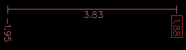
3.3.3. Program Extents
The "extents" of the program in each axis are shown. At each end, the least or greatest coordinate value is indicated. In the middle, the difference between the coordinates is shown. In Figure ( [cap:AXIS-Window]), the X extent of the file is from 0.00 to 6.92 inches, a total of 6.92 inches.
When some coordinates exceed the "soft limits" in the .ini file, the relevant dimension is shown in a different color and enclosed by a box. In Figure ( [cap:Soft-Limit]) the maximum soft limit is exceeded on the X axis as indicated by the box surrounding the coordinate value.
3.3.4. Tool Cone
The location of the tip of the tool is indicated by the "tool cone". The cone does not indicate anything about the shape, length, or radius of the tool.
When a tool is loaded (for instance, with the MDI command T1M6 ), the cone changes to a cylinder which shows the diameter of the tool given in the tool table file.
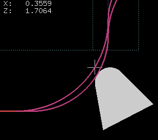
3.3.5. Backplot
When the machine moves, it leaves a trail called the backplot. The color of the line indicates the type of motion: Yellow for jogs, faint green for rapid movements, red for straight moves at a feed rate, and magenta for circular moves at a feed rate.
3.3.6. Interacting
By left-clicking on a portion of the preview plot, the line will be highlighted in both the graphical and text displays. By left-clicking on an empty area, the highlighting will be removed.
By dragging with the left mouse button pressed, the preview plot will be shifted (panned).
By dragging with shift and the left mouse button pressed, or by dragging with the mouse wheel pressed, the preview plot will be rotated. When a line is highlighted, the center of rotation is the center of the line. Otherwise, the center of rotation is the center of the file as a whole.
By rotating the mouse wheel, or by dragging with the right mouse button pressed, or by dragging with control and the left mouse button pressed, the preview plot will be zoomed in or out.
By clicking one of the "Preset View" icons, or by pressing "V", several preset views may be selected.
3.4. Text Display Area
By left-clicking a line of the program, the line will be highlighted in both the graphical and text displays in blue.
When the program is running, the line currently being executed is highlighted in red. If no line has been selected by the user, the text display will automatically scroll to show the current line.
3.5. Manual Control
While the machine is turned on but not running a program, the items in the "Manual Control" tab can be used to move the machining center or turn different parts of it on and off.
When the machine is not turned on, or when a program is running, the manual controls are unavailable.
Many of the items described below are not useful on all machines. When AXIS detects that a particular pin is not connected in HAL, the corresponding item in the Manual Control tab is removed. For instance, if the HAL pin motion.spindle-brake is not connected, then the "Brake" button will not appear on the screen. If the environment variable AXIS_NO_AUTOCONFIGURE is set, this behavior is disabled and all the items will appear.
3.5.1. The "Axis" group
"Axis" allows you to manually move the machine. This action is known as "jogging". First, select the axis to be moved by clicking it. Then, click and hold the "+" or "-" button depending on the desired direction of motion. The first four axes can also be moved by the arrow keys (X and Y), PAGE UP and PAGE DOWN keys (Z) and the [ and ] keys (A).
If "Continuous" is selected, the motion will continue as long as the button or key is pressed. If another value is selected, the machine will move exactly the displayed distance each time the button is clicked or the key is pressed. By default, the available values are:
0.1000, 0.0100, 0.0010, 0.0001
See the Configure section of the Integrators Manual for more information on setting the increments.
3.5.2. Homing
If your machine has home switches and a homing sequence defined for all axes the button will read "Home All". The "Home All" button or the Ctrl-HOME key will home all axes using the homing sequence. Pressing the HOME key will home the current axis, even if a homing sequence is defined.
If your machine has home switches and no homing sequence is defined or not all axes have a homing sequence the button will read "Home" and will home the selected axis only. Each axis must be selected and homed separately.
If your machine does not have home switches defined in the configuration the "Home" button will set the current selected axis current position to be the absolute position 0 for that axis and will set the "is-homed" bit for that axis.
See the Integrators Manual for more information on homing.
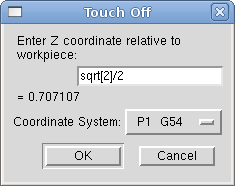
3.5.3. Touch Off
By pressing "Touch Off" or the END key, the "G54 offset" for the current axis is changed so that the current axis value will be the specified value. Expressions may be entered using the rules for rs274ngc programs, except that variables may not be referred to. The resulting value is shown as a number.
3.5.4. Override Limits
By pressing "Override Limits", the machine will temporarily be allowed to jog off of a physical limit switch. This check box is only available if a limit switch is tripped.
3.5.5. The "Spindle" group
The buttons on the first row select the direction for the spindle to rotate: Counterclockwise, Stopped, Clockwise. Counterclockwise will only show up if the pin motion.spindle-reverse is in the hal file (it can be net trick-axis motion.spindle-reverse ). The buttons on the next row increase or decrease the rotation speed. The checkbox on the third row allows the spindle brake to be engaged or released. Depending on your machine configuration, not all the items in this group may appear. Pressing the spindle start button sets the "S" speed to 1.
3.5.6. The "Coolant" group
The two buttons allow the "Mist" and "Flood" coolants to be turned on and off. Depending on your machine configuration, not all the items in this group may appear.
3.6. MDI
MDI, allows G-code programs can be entered manually, one line at a time. When the machine is not turned on, or when a program is running, the MDI controls are unavailable.
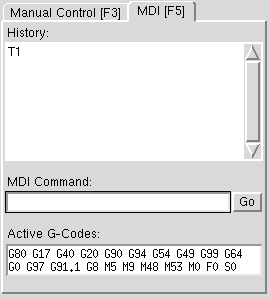
- History
-
This shows MDI commands that have been typed earlier in this session.
- MDI Command
-
This allows you to enter a g-code command to be executed. Execute the command by pressing Enter or by clicking "Go".
- Active G-Codes
-
This shows the "modal codes" that are active in the interpreter. For instance, "G54" indicates that the "G54 offset" is applied to all coordinates that are entered. When in Auto the Active G-Codes represent the codes after any read ahead by the interpreter.
3.7. Feed Override
By moving this slider, the programmed feed rate can be modified. For instance, if a program requests F60 and the slider is set to 120%, then the resulting feed rate will be 72.
3.8. Spindle Speed Override
By moving this slider, the programmed spindle feed rate can be modified. For instance, if a program requests F8000 and the slider is set to 80%, then the resulting spindle speed will be 6400. This item only appears when the HAL pin motion.spindle-speed-out is connected.
3.9. Jog Speed
By moving this slider, the speed of jogs can be modified. For instance, if the slider is set to 1 in/min, then a .01 inch jog will complete in about .6 seconds, or 1/100 of a minute. Near the left side (slow jogs) the values are spaced closely together, while near the right side (fast jogs) they are spaced much further apart, allowing a wide range of jog speeds with fine control when it is most important.
On machines with a rotary axis, a second jog speed slider is shown. This slider sets the jog rate for the rotary axes (A, B and C).
3.10. Max Velocity
By moving this slider, the maximum velocity can be set. This caps the maximum velocity of axis no matter what is programed in the g code file.
4. Keyboard Controls
Almost all actions in AXIS can be accomplished with the keyboard. A full list of keyboard shortcuts can be found in the AXIS Quick Reference, which can be displayed by choosing Help > Quick Reference. Many of the shortcuts are unavailable when in MDI mode.
4.0.1. Feed Override Keys
The Feed Override keys behave differently when in Manual Mode. The keys `12345678 will select an axis if it is programed. If you have 3 axis then ` will select axis 0, 1 will select axis 1 and 2 will select axis 2. The remainder of the number keys will still set the Feed Override. When running a program `1234567890 will set the Feed Override to 0% - 100%.
The most frequently used keyboard shortcuts are shown in Table [cap:Most-Common-Keyboard].
5. Show EMC Status
AXIS includes a program called "emctop" which shows some of the details of EMC’s state. You can run this program by invoking Machine > Show EMC Status
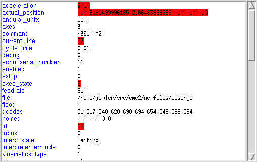
The name of each item is shown in the left column. The current value is shown in the right column. If the value has recently changed, it is shown on a red background.
6. MDI interface
AXIS includes a program called "MDI" which allows text-mode entry of MDI commands to a running EMC session. You can run this program by opening a terminal and typing
mdi /path/to/emc.nml
Once it is running, it displays the prompt MDI> . When a blank line is entered, the machine’s current position is shown. When a command is entered, it is sent to EMC to be executed.
This is a sample session of mdi.
$ mdi ~/emc2/configs/sim/emc.nml  +
MDI>  +
(0.0, 0.0, 0.0, 0.0, 0.0, 0.0) +
MDI> G1 F5 X1 +
MDI>  +
(0.5928500000000374, 0.0, 0.0, 0.0, 0.0, 0.0) +
MDI>  +
(1.0000000000000639, 0.0, 0.0, 0.0, 0.0, 0.0)
7. axis-remote
AXIS includes a program called "axis-remote" which can send certain commands to a running AXIS. The available commands are shown by running axis-remote ---help and include checking whether AXIS is running (---ping), loading a file by name, reloading the currently loaded file (---reload), and making AXIS exit (---quit).
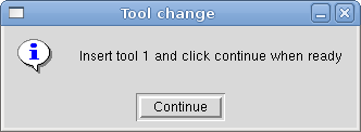
8. Manual Tool Change
EMC2 includes a userspace hal component called "hal_manualtoolchange", which shows a window (Figure [cap:The-Manual-Toolchange]) when a M6 command is issued. After the OK button is pressed, execution of the program will continue.
The HAL configuration file configs/sim/axis_manualtoolchange.hal shows the HAL commands necessary to use this component.
hal_manualtoolchange can be used even when AXIS is not used as the GUI. This component is most useful if you have presettable tools and you use the tool table.
Important Note: Rapids will not show on the preview after a T<n> is issued until the next feed move after the M6. This can be very confusing to most users. To turn this feature off for the current tool change program a G1 with no move after the T<n>.
9. Python modules
AXIS includes several Python modules which may be useful to others. For more information on one of these modules, use "pydoc <module name>" or read the source code. These modules include:
-
emc provides access to the emc command, status, and error channels
-
gcode provides access to the rs274ngc interpreter
-
rs274 provides additional tools for working with rs274ngc files
-
hal allows the creation of userspace HAL components written in Python
-
_togl provides an OpenGL widget that can be used in Tkinter applications
-
minigl provides access to the subset of OpenGL used by AXIS
To use these modules in your own scripts, you must ensure that the directory where they reside is on Python’s module path. When running an installed version of EMC2, this should happen automatically. When running "in-place", this can be done by using scripts/emc-environment.
10. Lathe Mode
By including the line
LATHE=1
in the [DISPLAY] section of the ini file, AXIS selects lathe mode. The "Y" axis is not shown in coordinate readouts, the view is changed to show the Z axis extending to the right and the X axis extending towards the bottom of the screen, and several controls (such as those for preset views) are removed.
Pressing "V" zooms out to show the entire file, if one is loaded.
When in lathe mode, the shape of the loaded tool (if any) is shown.
11. Advanced Configuration
For more information on ini file settings that can change how AXIS works see the INI File/Sections/[DISPLAY] Section of Configuration chapter in the Integrators manual.
11.1. Program Filters
AXIS has the ability to send loaded files through a "filter program". This filter can do any desired task: Something as simple as making sure the file ends with 'M2 ', or something as complicated as detecting whether the input is a depth image, and generating g-code to mill the shape it defines.
The [FILTER] section of the ini file controls how filters work. First, for each type of file, write a PROGRAM_EXTENSION line. Then, specify the program to execute for each type of file. This program is given the name of the input file as its first argument, and must write rs274ngc code to standard output. This output is what will be displayed in the text area, previewed in the display area, and executed by EMC when "Run". The following lines add support for the "image-to-gcode" converter included with EMC2:
[FILTER] +
PROGRAM_EXTENSION = .png,.gif Greyscale Depth Image +
png = image-to-gcode +
gif = image-to-gcode
It is also possible to specify an interpreter:
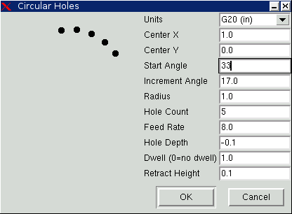
PROGRAM_EXTENSION = .py Python Script +
py = python
In this way, any Python script can be opened, and its output is treated as g-code. One such example script is available at nc_files/holecircle.py . This script creates g-code for drilling a series of holes along the circumference of a circle.
If the environment variable AXIS_PROGRESS_BAR is set, then lines written to stderr of the form
FILTER_PROGRESS=%d
will set the AXIS progress bar to the given percentage. This feature should be used by any filter that runs for a long time.
11.2. The X Resource Database
The colors of most elements of the AXIS user interface can be customized through the X Resource Database. The sample file axis_light_background changes the colors of the backplot window to a "dark lines on white background" scheme, and also serves as a reference for the configurable items in the display area. The sample file axis_big_dro changes the position readout to a larger size font. To use these files:
xrdb -merge /usr/share/doc/emc2/axis_light_background
xrdb -merge /usr/share/doc/emc2/axis_big_dro
For information about the other items which can be configured in Tk applications, see the Tk man pages.
Because modern desktop environments automatically make some settings in the X Resource Database that adversely affect AXIS, by default these settings are ignored. To make the X Resource Database items override AXIS defaults, include the following line in your X Resources:
*Axis*optionLevel: widgetDefault
this causes the built-in options to be created at the option level "widgetDefault", so that X Resources (which are level "userDefault") can override them.
11.3. Physical jog wheels
To improve the interaction of AXIS with physical jog wheels, the axis currently selected in the GUI is also reported on a pin with a name like axisui.jog.x . Except for a short time when the active axis has just been changed, exactly one of these pins is TRUE at one time, and the rest are FALSE.
After AXIS has created these HAL pins, it executes the halfile named in [HAL]POSTGUI_HALFILE. Unlike [HAL]HALFILE, only one such file may be used.
11.4. axisrc
If it exists, the contents of ~/.axisrc are executed as Python source code just before the AXIS gui is displayed. The details of what may be written in the axisrc are subject to change during the development cycle.
The following adds Control-Q as a keyboard shortcut for Quit and turns on "Distance to go" by default.
root_window.bind("<Control-q>", "destroy .") +
help2.append(("Control-Q", "Quit")) +
vars.show_distance_to_go.set(1)
11.5. External Editor
The menu options File > Edit… and File > Edit Tool Table… become available after defining the editor in the ini section [DISPLAY]. Useful values include EDITOR=gedit and EDITOR=gnome-terminal -e vim. For more information, see the DISPLAY section of the INI Configuration Chapter in the Integrators Manual.
11.6. Virtual Control Panel
AXIS can display a custom virtual control panel in the right-hand pane. You can program buttons, indicators, data displays and more. For more information, see the Integrators Manual.
11.7. Special Comments
Special comments can be inserted into the G Code file to control how the preview of AXIS behaves. In the case where you want to limit the drawing of the preview use these special comments. Anything between the (AXIS,hide) and (AXIS,show) will not be drawn during the preview. The (AXIS,hide) and (AXIS,show) must be used in pairs with the (AXIS,hide) being first. Anything after a (AXIS,stop) will not be drawn during the preview.
These comments are useful to unclutter the preview display (for instance while debugging a larger g-code file, one can disable the preview on certain parts that are already working OK).
-
(AXIS,hide) Stops the preview (must be first)
-
(AXIS,show) Resumes the preview (must follow a hide)
-
(AXIS, stop) Stops the preview from here to the end of the file.