Back
[00:03:54] <theorb> theorb is now known as theorbtwo
[00:45:49] <Gangsta> hi
[00:47:02] <Gangsta> I have emc running on my lathe, and now im trying to display the spindle speed on axis, can anyone help or point me in the right direction? thanks
[01:07:59] <spasticteapot> Does anyone here have any use for a low-end PC104-compatible single-board computer?
[01:08:06] <spasticteapot> I think it has a K6-II @ 300mhz.
[01:23:04] <foxtrot> i have an I-Opener
[01:23:09] <foxtrot> i dont know if you remember those
[01:30:54] <spasticteapot> foxtrot: I do, actually.
[01:31:05] <spasticteapot> I'm not sure if there's any PC104-specific hardware for milling machines.
[01:31:09] <spasticteapot> I just want to get rid of the sillying thing.
[01:33:46] <tom3p> mesa has some pc104 motion control cards.
[01:33:46] <tom3p> if your card has enuf mem, maybe you can run a linux with emc2 on it.
[01:34:07] <tom3p> and hook it to the pc104 mesa cards
[01:36:53] <tom3p> i changed a system from crt to lcd, and it wont run any GL now (yet did before).
[01:36:53] <tom3p> GLXgears is a black box, AXIS is blank BG color where the 3D display ought to be. no errors!
[01:41:23] <The_Ball> cradek, 4-5hours, that's quite efficient :)
[01:49:29] <spasticteapot> I don't really need it for anything - I'm just hoping I can trade it to someone for some CNCd PCBs or something.
[02:08:41] <madsci44> you are looking for cnc'd pcb's spasticteapot?
[02:08:53] <spasticteapot> I'd like one or two.
[02:09:11] <madsci44> im finishing a machine for that in the next couple days im hoping
[02:09:15] <spasticteapot> I'm kinda short on cash, and commercial PCBs are a bit spendy.
[02:09:18] <spasticteapot> Anything you want in trade?
[02:10:21] <madsci44> not sure off the top of my head, but i wouldnt mind doing a couple if you need
[02:10:43] <madsci44> more to test with :)
[02:11:00] <spasticteapot> Fair 'nuff.
[02:11:02] <elmo40> an opto-isolator? but how would that control the motor digitally?
[02:11:28] <spasticteapot> What kind of precision is your machine good for?
[02:11:53] <madsci44> i think he meant use the optoisolator's transistor to do the action of the pot - and then you could drive it with an analog input voltage/current
[02:12:11] <spasticteapot> All the pieces on mine are through-hole, but some of the clearances are a bit fiddly.
[02:12:15] <madsci44> im hoping I'll be able to pull off 0.005 mark/space
[02:13:47] <madsci44> the positional resolution is of course much higher - perhaps 0.0005 and its a very rigid setup
[02:14:44] <madsci44> im going to try by coating it , "machining" that off and then etching
[02:14:59] <spasticteapot> That'll do it.
[02:15:23] <spasticteapot> I'd go for direct machining, though - all sorts of headaches happen when you etch.
[02:16:07] <madsci44> yeah i will try that too - i need more experience to see what limits I can get out of it , I have alot of experience with etching so that should be ok for the moment
[02:16:58] <spasticteapot> Fair enough.
[02:17:11] <spasticteapot> Have you considered nickel plating?
[02:17:29] <madsci44> no should i ?
[02:17:32] <spasticteapot> It's not that difficult, and it should do a nice job of preventing corrosion.
[02:17:36] <spasticteapot> Probably overkill, though.
[02:20:03] <madsci44> i used to use this "liquid tin" stuff - just soak for a few seconds and it tin plates, but over long term i have found it tarnishes about as much as the copper. I wouldnt mind trying some sort of resilient plating for contacts
[02:27:39] <The_Ball> i had to fix my server's hdd, the contacts which connect to the hdd's heads were corroded, cleaned with acetone didn't help, had to re-tin with solder to get it back to life
[02:28:07] <The_Ball> i had to fix my server's hdd, the contacts which connect to the hdd's heads were corroded, cleaned with acetone didn't help, had to re-tin with solder to get it back to life
[02:28:19] <The_Ball> sorry, wrong window (up - enter)
[02:28:37] <madsci44> np
[02:28:38] <madsci44> np
[02:28:46] <spasticteapot> madsci44: Gold works nicely.
[02:28:50] <spasticteapot> Nickel too.
[02:29:05] <The_Ball> i always seem to misplace my gold solder though
[02:29:12] <spasticteapot> Nickel is cheaper - all you need is nickel sulfate and boric acid for a reasonably good plating.
[02:29:14] <madsci44> lol
[02:29:33] <madsci44> does nickel solder as reliably ?
[02:29:35] <spasticteapot> And since it's one of the main ingredients of solder, you shouldn't have any problems using it.
[02:29:46] <madsci44> ic
[02:29:49] <spasticteapot> Isn't most solder 15-25% nickel?
[02:30:01] <spasticteapot> At least, the lead-based stuff usually is.
[02:33:05] <madsci44> well i still use lead based stuff - but that's only tin/lead - as for the lead-free ones i'm not sure
[02:35:52] <madsci44> nickel plate would be handy for many things tho - maybe i will try that soon
[03:51:29] <genehacker_> genehacker_ is now known as genehacker
[04:05:46] <elmo40> is 1Hp strong enough for a direct drive lathe? I am thinking of a more compact design and pulleys just get in the way ;) I may have a lead on a 2.5Hp motor, though I currently have a 1Hp DC motor.
[04:12:24] <cradek> maybe for small diameters
[04:12:40] <cradek> direct drive means going slow sucks
[04:14:07] <cradek> first time you want to cut 6" dia of steel and you find you have to do it at 80 rpm...
[04:28:56] <elmo40> I suppose...
[04:29:08] <elmo40> then again, that is why they made Ceramic inserts ;)
[04:29:28] <elmo40> higher speeds, no coolant required.
[04:34:48] <elmo40> maybe I can redesign... it is a little iffy at lower speeds. not sure what the lowest speed is, though.
[04:50:26] <elmo40> what is 25 in.lbs. in ounces?
[04:53:35] <elmo40> JT-Work: that box, INS:B6, I think that is the insulation class.
[05:10:21] <geo01005_home> geo01005_home is now known as geo01005
[10:06:56] <Fox_M|afk> Fox_M|afk is now known as Fox_Muldr
[12:55:48] <Optic> moo
[13:05:05] <elmo40> http://www.omegaebr.com/
[13:51:21] <alex_joni> Optic: wb
[13:51:30] <Optic> thanks :)
[15:16:26] <ichudov> q
[15:21:40] <ichudov_> I have a few Qs about tuning servo loops. Guys, does anyone know what does it mean to have a "well tuned" system, when it comes to tuning servos? Whhat does it mean well tuned? How do I practically know that my servo motors/drives/etc are "well tuned"?
[15:22:11] <ichudov_> I mean, my servo motors do not vibrate as much as they used to, except after rapid moves, but is my system well tuned?
[15:28:10] <cradek> if they oscillate after rapid moves tuning can probably be improved
[15:29:55] <ichudov_> cradek: I agree. My servos are run in "velocity mode". So the drives have their own gain setting to manage the velocity loop. Then, EMC has its own positioning loop. In addition, the drives have a setting to change "reference signal gain" to change how fast they respond to the signals from EMC. I tried following a procedure to set gain on the drive first, and then adjust P,I,D, but generally I never really was successful
[15:30:30] <ichudov_> I mean, the mill is usable, but I just do not know how good it is. To reduce all that vibration I have to turn all gains WAY down
[15:30:41] <skunkworks_> ichudov_: are you using the original amps or pico systems?
[15:31:19] <cradek> sounds like you don't know which loop is oscillating. you should tune the velocity loop in the amps first, using the procedure in the amp manual
[15:31:19] <skunkworks_> ichudov_: have you looked at your following error?
[15:31:41] <ichudov_> I sold original drives. I am using A-M-C 30A8T drives:
http://www.a-m-c.com/download/datasheet/40a20.pdf
[15:31:56] <skunkworks_> cradek: any progress on the stirling engine?
[15:32:09] <ichudov_> OOPS!
http://www.a-m-c.com/download/datasheet/40a20.pdf
[15:32:13] <cradek> no, I made dominoes instead of working on it
[15:32:19] <skunkworks_> heh
[15:32:33] <cradek> I can't finish anything that takes longer than one day to do
[15:32:53] <ichudov_> skunkworks_: I looked at my following error too. In is lower now (0.005 or some values like this) but I could never get it low
[15:33:05] <ichudov_> and sometimes it is higher
[15:33:23] <skunkworks_> .005? inch? that seems way too high.
[15:33:32] <ichudov_> I agree
[15:33:47] <ichudov_> This is a good machine and I would like to tune it really well
[15:34:12] <cradek> sounds like you don't know which loop is oscillating. you should tune the velocity loop in the amps first, using the procedure in the amp manual
[15:34:34] <cradek> tuning the position loop in emc is a waste of time if the velocity loop is not tuned
[15:34:37] <skunkworks_> tuning is one of those things that is hard to teach. You just need to do it... - and as cradek said - tune the velocity loop first.
[15:35:01] <cradek> actually, this is one reason why it's good to keep the original amps and motors together when retrofitting a machine
[15:35:29] <ichudov_> skunkworks_:This, I can generally do: turn velocity gain up until motors start to vibrate, then turn it down two turns
[15:36:00] <ichudov_> cradek: one of the original drives was bad (my fsck up). Also they were of weird 380 volt type.
[15:37:16] <JT-Work> my drives are 380 volts
[15:37:23] <ichudov_> I took all old stuff out more or less
[15:38:41] <ichudov_> I can tune amps, yes. I guess I should perhaps just dedicate an evening to it and redo everything carefully. What I do not know is, mainly, what is a "well tuned system" and is there some measurable value that I can look at to see if I did a good job
[15:38:56] <ichudov_> JT-Work: what is your machine
[15:39:18] <JT-Work> CHCN Hardinge
[15:39:25] <ichudov_> nice!
[15:39:30] <cradek> a well tuned mill should maintain following error to 10-20 encoder counts during all motion including rapids
[15:39:55] <ichudov_> cradek: this is very useful. Thanks
[15:39:57] <cradek> or if not, it should be as good as possible
[15:40:25] <cradek> I'm not sure it's really that useful, actually, but you wanted a definition and that's the best I can do
[15:40:33] <ichudov_> That's a start anyway
[15:40:37] <cradek> yeah
[15:41:00] <ichudov_> I think that I will spend my evening just tuning this. There is also this feature on the drives called "Test/Offset" that has been driving me nuts.
[15:41:20] <cradek> that's the balance control
[15:41:28] <ichudov_> I would adjust it for low creep, and two days later it creeps more again
[15:41:29] <ichudov_> yes
[15:41:44] <cradek> it won't creep while the position loop is closed
[15:41:53] <ichudov_> yes, but servos jerk
[15:42:03] <cradek> it doesn't matter if there's a tiny bit of creep with the loop open, and you're right it'll change (a bit) over time
[15:42:08] <cradek> what do you mean?
[15:42:25] <ichudov_> The motor creeps, and then EMC jerks it back and there are some oscillations
[15:42:33] <ichudov_> Less creep, less jerking
[15:43:20] <ichudov_> Like I said, I can use this mill, I just know that it is not really up to the standard.
[15:43:44] <cradek> it should never creep. you have something misconfigured if it creeps in normal operation
[15:44:03] <cradek> do you have amp enable hooked up so "machine off" disables the amps?
[15:44:09] <ichudov_> When position loop is closed, it does not creep over long distances. It would just creep a bit and EMC jerks it back.
[15:44:29] <ichudov_> a bit is really a very smnall creep, like 1 angular degree on the motor or some such.
[15:45:00] <ichudov_> cradek: I do not have "amp enable" wired to inhibits, yet, but I will do it.
[15:45:19] <ichudov_> This is just an indication that tuning leaves much to be desired, that I did not do a good job
[15:48:01] <ichudov_> Anyway, I will work some more on this tonight
[16:02:41] <morficmobile> cradek: the hal component you refered to is what comp creates, correct?
[16:06:30] <cradek> ?
[16:10:18] <morficmobile> was asking if you meant hal user manual section 6.1 and below when you said "would require a hal compenent" when i asked about doing stuff with adc
[16:11:53] <Jymmm> Morning
[16:18:35] <skunkworks_> barely
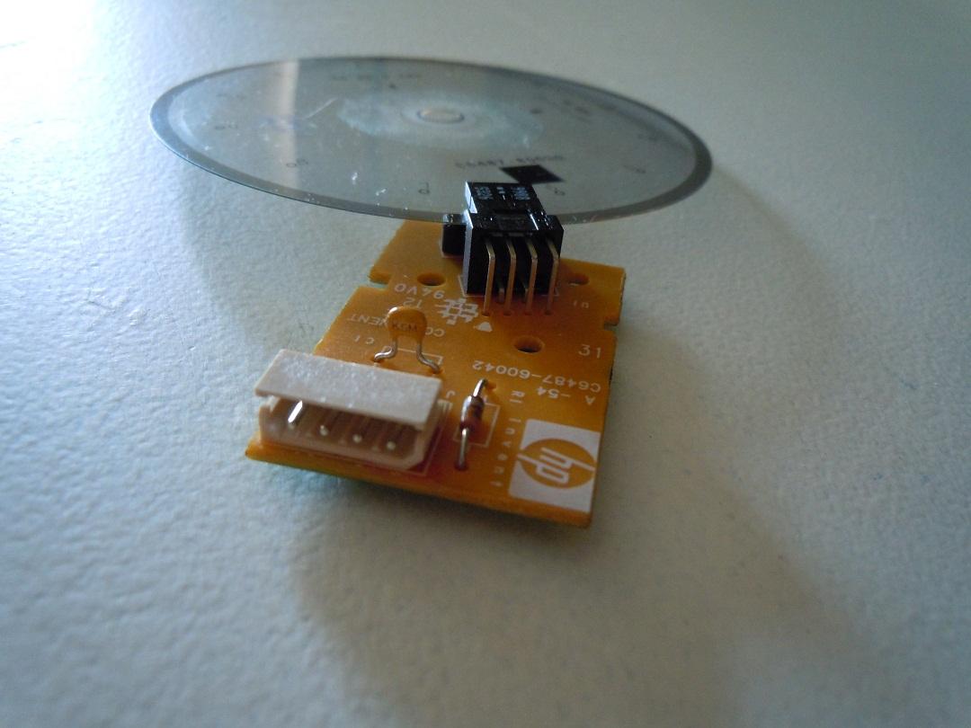
[16:22:04] <elmo40> I tore apart my HP printer-scanner dealy. It has a very useful component in it... if I knew how to connect it to EMC ;)
http://image.bayimg.com/naohaaacb.jpg
[16:29:12] <cpresser_> read the datasheet of the optical component :)
[16:30:20] <cpresser_> or isnt it an optical encoder?
[16:32:04] <cpresser_> you could also put it back into the printer and check its signals with a scope
[16:32:20] <cpresser_> most likely it will just generate square-wave-pulses
[16:32:36] <cpresser_> which is perfect for emc :)
[16:37:53] <morficmobile> cradek: sorry, thought boss said he wanted everything answered today...i did freak *a little*....but, i do have until next week, so hopefully i find what i need in the docs
[16:39:26] <skunkworks_> wonder how many line that is. Maybe 500?
[16:39:43] <skunkworks_> 1000 edges?
[16:39:53] <skunkworks_> heh * 2000 edges
[16:44:21] <foxtrot_lab> I fixed 1/2 of my broken drivers!
[16:44:31] <foxtrot_lab> so ive got a 3axis cnc again
[16:44:51] <foxtrot_lab> except for some reason the Y motor driver (bipolar stepper) is like 5x hotter than Z or X
[16:45:25] <foxtrot_lab> and im still getting that thing usually when i try to start a job where the Z will try to move down but just like make a squeeling sound instead and miss the whole movement
[16:45:52] <elmo40> foxtrot_lab: nice.
[16:46:00] <elmo40> how did you get the Z working again?
[16:56:35] <foxtrot_lab> lifted trace
[16:56:49] <foxtrot_lab> finally got it to work again, was about to order new drivers
[16:56:56] <foxtrot_lab> the Z stil has that torque issue
[16:57:09] <foxtrot_lab> maybe its just my settings in emc for override/velocity/etc
[16:57:27] <foxtrot_lab> whats something not too taxing for a crapjob like my machine
[16:57:50] <foxtrot_lab> my Zaxis motor only has 60oz/in holding torque
[17:00:20] <foxtrot_lab> like i think i could mill something by manually jogging the axises almost heh]
[17:00:40] <foxtrot_lab> drivers might just be shot and overheating/malfunctioning
[17:00:46] <foxtrot_lab> i got the IC way to hot a ton of times
[17:00:58] <foxtrot_lab> but it does... work
[17:01:19] <foxtrot_lab> i just cant get all my axises moving in union
[17:01:30] <foxtrot_lab> a magical CNC fantasia
[17:02:08] <elmo40> cpresser_: it is an Agilent optical component. I have tried searching all the numbers on the device (9988 and s326) to no avail. From the looks of the circuit it seems there is a power supply, possibly < 5V, and two other leads, presumably the signal. I guess picking up a scope is the next step ;)
[17:02:54] <elmo40> foxtrot_lab: have you ever been able to get them all moving in unison?
[17:03:12] <elmo40> if not, it could be a weak power supply not being able to handle the current demand.
[17:06:40] <elmo40> preliminary guestimation on the number of lines in the disc is 600... need to locate my magnifying glass and make lines.
[17:10:48] <elmo40> many sites say it is a 'PPR ENCODER PCA' now, what does that mean?
[17:12:04] <foxtrot_lab> its an ATX PSU
[17:12:24] <foxtrot_lab> its odd that one driver would be much hotter than others tho
[17:13:43] <foxtrot_lab> in generaL: x to right is +, Y north is +, and Z up is +
[17:13:44] <foxtrot_lab> right
[17:19:15] <elmo40> it can be many ways... it doesn't really matter ;)
[17:35:30] <foxtrot_lab> hmm
[17:35:36] <foxtrot_lab> i wish i knew where to go from here
[17:35:46] <foxtrot_lab> ive done everything i can
[17:35:56] <foxtrot_lab> the motors are running at full current, half voltage
[17:36:03] <foxtrot_lab> (9.5v instead of 24v)
[17:36:24] <foxtrot_lab> and they are already getting super hot, imagine if i did put a 24v supply on there
[17:36:43] <IchGuckLive> more volt less heat
[17:36:53] <foxtrot_lab> really
[17:37:01] <IchGuckLive> the current produces the head
[17:37:29] <IchGuckLive> 36V 2,5A 15°C
[17:37:40] <IchGuckLive> 12V 2,5A 40°C
[17:37:52] <foxtrot_lab> so going from 9.5v 2A to 24v 2A will help with cooling?
[17:38:00] <IchGuckLive> on 10min mill#
[17:38:21] <IchGuckLive> yes offcause
[17:38:40] <IchGuckLive> more speed also
[17:39:26] <foxtrot_lab> wow awesome
[17:39:30] <elmo40> exactly. drop the current and you drop the heat.
[17:39:32] <foxtrot_lab> maybe this will solve all my torque issues
[17:39:35] <IchGuckLive> are the motors 2A or only 1,2A
[17:39:49] <foxtrot_lab> they are 1A per coil
[17:40:15] <IchGuckLive> so give them 800mA
[17:40:26] <IchGuckLive> 24V
[17:40:39] <IchGuckLive> and you camn mill 8hr
[17:41:22] <foxtrot_lab> wait they are actually 2A/phase
[17:41:26] <foxtrot_lab> whatever that means
[17:41:51] <foxtrot_lab> so up the voltage and drop the current?
[17:41:52] <IchGuckLive> so give it a start at 1.5A
[17:42:11] <IchGuckLive> try to move Half step
[17:42:51] <foxtrot_lab> my drivers have current pots and can do up to 2A per coil
[17:42:53] <IchGuckLive> witch driver do you use
[17:42:59] <foxtrot_lab> per coil = per phase?
[17:43:10] <IchGuckLive> the same
[17:43:12] <JT-Work> foxtrot_lab:
http://wiki.linuxcnc.org/cgi-bin/emcinfo.pl?Stepper_Formulas
[17:43:16] <foxtrot_lab> http://www.pololu.com/file/0J199/a4983_DMOS_microstepping_driver_with_translator.pdf
[17:44:26] <foxtrot_lab> ive been tweaking for months i just never make any real progress
[17:44:34] <foxtrot_lab> i feel like im so close this time
[17:44:48] <foxtrot_lab> should i seperate the motor gnd and logic gnd
[17:44:58] <foxtrot_lab> or just tie them at one point
[17:46:29] <foxtrot_lab> also, im full stepping
[17:46:30] <IchGuckLive> page6 table1 how are you connected
[17:46:49] <foxtrot_lab> could that lead to torque losses and squeeks
[17:46:53] <IchGuckLive> full step is not good for the driverboard
[17:48:53] <foxtrot_lab> how about half step then
[17:48:58] <IchGuckLive> ok
[17:49:31] <foxtrot_lab> could that be factoring in my torque problem you think?
[17:49:51] <Jymmm> https://spreadsheets.google.com/viewform?hl=en&formkey=dGU2V0ZUQ1g3NHRzNkloT1hGOEhjVUE6MQ#gid=0
[17:49:52] <IchGuckLive> thourqe is power problem
[17:50:11] <IchGuckLive> to low voltige supply
[17:50:33] <IchGuckLive> if you go on 24V this will be history
[17:50:36] <elmo40> the power supply is how many Watts?
[17:51:05] <elmo40> you said it is an ATX power supply. I have one at 300W working 110oz.in motors no problem.
[17:51:08] <foxtrot_lab> i have an unused 24v 6.5A 150w supply
[17:51:23] <IchGuckLive> this will work
[17:51:37] <foxtrot_lab> but this ATX supply is 250 watts and seems broken because yellow is only 9.5v
[17:51:40] <IchGuckLive> the Resistor for the ref how many oms
[17:51:55] <IchGuckLive> <0,5?
[17:52:10] <foxtrot_lab> i dont have one i dont think
[17:52:30] <IchGuckLive> so you got no current controle at all
[17:52:50] <foxtrot_lab> just variable resistors on each driver
[17:53:01] <Jymmm> bad idea
[17:53:18] <Jymmm> they tend to drift when you least expect it
[17:53:23] <foxtrot_lab> so my motors are 2a a coil and my driver supports 2a a coil why not just turn it all the way up
[17:54:08] <bootnecklad> oh oh oh! pick me! unrelated CNC but:
http://www.youtube.com/user/bootnecklad#g/c/02ED71412E1E41AA
[17:54:10] <bootnecklad> :D
[17:54:19] <bootnecklad> pjm__ ^
[17:54:28] <Gangsta> hi
[17:54:41] <IchGuckLive> foxtrot_lab: this is not LEGO
[17:55:08] <IchGuckLive> you got to calculaste the Current and do some adjust
[17:55:26] <IchGuckLive> Sensor resitor 3W 0,47Ohm
[17:55:26] <foxtrot_lab> the ideal current or the calculated current
[17:55:49] <foxtrot_lab> ive only got 10W 10ohm power resistors
[17:56:26] <Gangsta> can anyone tell me how to display the actual spindle speed, taken from the Spindle Index input pin?
[17:56:31] <IchGuckLive> then the Ref calculatet by formula
[17:57:14] <foxtrot_lab> should i put a cap between +/- on the 24v supply before i connect it to the Vmotor/motor gnd. and should i tie motor gnd to logic ground or?
[17:58:22] <IchGuckLive> yes 2200µF
[17:58:28] <foxtrot_lab> those are the only things i dont know holding me up
[17:58:40] <foxtrot_lab> 2200uF? what voltage?
[17:58:47] <Gangsta> whats people chattin about? I missed the start of the convo
[17:59:15] <IchGuckLive> ref=I(coil)*R(sense)*sqrt(2)
[17:59:26] <foxtrot_lab> ive got a 2200uF 50v
[17:59:33] <IchGuckLive> ok
[17:59:37] <micges> logger_emc: bookmark
[17:59:37] <micges> Just this once .. here's the log:
http://www.linuxcnc.org/irc/irc.freenode.net:6667/emc/2010-08-03.txt
[17:59:50] <micges> Gangsta: check log ^^
[18:00:06] <Gangsta> cheers :D
[18:00:27] <foxtrot_lab> what about tieing the logic and motor gnds to common gnd
[18:01:00] <IchGuckLive> is there a pc on the logic or just a microcontroller
[18:01:27] <foxtrot_lab> just the bipolar motor drivers
[18:01:38] <foxtrot_lab> 3 of them, plus a fan, thats it
[18:02:01] <IchGuckLive> the step and the dir signal comes from?
[18:02:54] <foxtrot_lab> the driver, each one (3 total) has Vcc,gnd,Vmot, gnd, MS1,Ms2,Ms3,en,step,dir
[18:04:01] <IchGuckLive> in the shematic there are more
[18:04:17] <foxtrot_lab> yeah it has all those
[18:04:24] <foxtrot_lab> i was just trying to point out the relevant ones
[18:04:46] <IchGuckLive> all those are requirert to get the system in a good shape and working mosde
[18:04:50] <IchGuckLive> mode
[18:05:03] <foxtrot_lab> http://www.pololu.com/picture/view/0J1418
[18:05:07] <IchGuckLive> you need all of them
[18:05:15] <foxtrot_lab> i think ive got all of them
[18:05:25] <foxtrot_lab> i mean my machine works as configured
[18:05:28] <foxtrot_lab> just not reliably
[18:05:32] <foxtrot_lab> or accurately
[18:05:53] <IchGuckLive> thatas what we try to find out of your answers
[18:06:06] <Gangsta> Can anyone help me display spindle speed?
[18:06:13] <IchGuckLive> sense resitors are ?
[18:06:46] <IchGuckLive> foxtrot_lab: maybe you are in sleep mode
[18:06:46] <foxtrot_lab> im pretty sure my wiring is good so far having the ATX PSU supply 12v,5v,and GND.... but I want to use my dedicated 24v 6.5A supply to power those motors that the 12v is powering now and keep using the ATX 5v for logic
[18:06:57] <foxtrot_lab> but they still work?
[18:07:15] <foxtrot_lab> ~RESENT is bridged to ~SLEEP
[18:07:21] <foxtrot_lab> on all of my drivers
[18:07:39] <IchGuckLive> Reset?
[18:07:45] <foxtrot_lab> yeah i meant that
[18:08:44] <foxtrot_lab> so whats my next move?
[18:08:59] <foxtrot_lab> seperate GNDs? gnds tied together?
[18:09:01] <IchGuckLive> put 5V at the sleep pin
[18:09:14] <IchGuckLive> over a 10Kohm resistor
[18:09:16] <foxtrot_lab> 2200uF cap going from Vmot to Vgnd
[18:09:28] <IchGuckLive> yes
[18:10:34] <IchGuckLive> also wire to half step
[18:11:56] <IchGuckLive> ref shoudt be 1,05V against Gnd
[18:11:58] <foxtrot_lab> ok
[18:12:13] <micges> Gangsta: check sim/lathe configuration, it has spindle speed indicator on pyvcp
[18:12:47] <IchGuckLive> foxtrot_lab: calculated on 0,47R at both sense
[18:13:25] <IchGuckLive> are the sense connectet to a big 2/3W resistor or open
[18:13:49] <foxtrot_lab> open
[18:14:01] <IchGuckLive> this will not work
[18:14:03] <foxtrot_lab> can i tie all the gnds together?
[18:14:13] <IchGuckLive> no
[18:14:24] <IchGuckLive> leave the gnd seperated
[18:14:30] <foxtrot_lab> ok
[18:15:00] <Gangsta> hi micges, I have tried that, but the displayed speed shows up and changes as I speed up/slow down my spindle (even with my sensor disabled), so it seems to be more of an requested speed display than an actual speed
[18:15:19] <IchGuckLive> the sence on the Driver eatch for a coil will with the Rev Voltage control the current and also the tourqu and the head of the motors
[18:16:03] <IchGuckLive> if you go without any control it will not work as you want it to work
[18:16:20] <micges> Gangsta: how can you read spindle speed?
[18:16:22] <skunkworks_> Gangsta: how is your spindle hooked into emc?
[18:16:51] <IchGuckLive> foxtrot_lab: no or only 15% tourqu
[18:17:25] <Gangsta> stepconf > Spindle_Index from the dropdown on the Parallel Port Page
[18:17:35] <IchGuckLive> foxtrot_lab: head allover cause there is no shoutdown level to reatch
[18:18:12] <IchGuckLive> foxtrot_lab: simply no control to the coil current
[18:18:51] <Gangsta> should it be Spindle_Phase_A? I have 48 pulses per rev on Phase_A and 1 pulse per rev on Index
[18:20:19] <IchGuckLive> foxtrot_lab: the Resistors are on the board
[18:26:05] <IchGuckLive> foxtrot_lab: ? still here
[18:26:45] <Gangsta> I have read back the log, but cant quite understand whats happening with foxtrot_lab. What is it thats not working?
[18:27:28] <IchGuckLive> Gangsta: he has simply no control and a high head problem
[18:28:13] <IchGuckLive> the Ref pin on his board controls the current of the motors but seams not to be connected
[18:28:58] <Gangsta> hmmm, is he using the onboard reg or a seperate one
[18:29:07] <IchGuckLive> iMotor=ref/(8*rd)
[18:29:41] <IchGuckLive> as i see the datasheet there are 2Rsens on the board
[18:30:14] <Gangsta> 2 Amp motors is that right?
[18:30:25] <IchGuckLive> also the sleep is not good conected on the board
[18:30:33] <IchGuckLive> yes
[18:30:59] <IchGuckLive> he has to messure the Rsense
[18:31:49] <Gangsta> sound like time to buy a new board (at around £20 it probaby not worth messing with for too long, as if the board is dodgy it a losing battle)
[18:32:30] <IchGuckLive> he did not read the datasheet
[18:32:50] <IchGuckLive> i baugt 3 boards for 5axis in Hongkong
[18:33:00] <Gangsta> so at 2A the pot should be adjusted till the voltage between REF and GND is 2.8v
[18:33:02] <IchGuckLive> at 65Euros eatch
[18:33:35] <IchGuckLive> where did you find the Rs ohm
[18:33:51] <Gangsta> the data
[18:33:59] <Gangsta> ..
[18:34:19] <alex_chally> today is going to be a boring day
[18:34:26] <alex_chally> * alex_chally gets to prepare stock
[18:34:28] <alex_chally> \o/
[18:34:53] <Gangsta> the datasheet says REF = Motor Current X 1.4
[18:35:16] <Gangsta> yay stock - i had to do stock today :(
[18:35:50] <alex_chally> i am making more bearing mounting blocks, which are made out of 2" thick 6" rounds
[18:36:02] <alex_chally> facing off 6" diameter steel takes a looooooooong time
[18:36:47] <Gangsta> lots more interesting that just sawing a couple hundred meters of ali extrusion for conservetory roofs
[18:37:54] <Gangsta> with a MANUAL chop saw (grrrr)
[18:38:20] <IchGuckLive> ok good night from germany
[18:38:45] <Gangsta> night mate, have a good one
[18:39:29] <alex_chally> Gangsta, 0.o
[18:39:37] <alex_chally> Gangsta, why do you not have a horizontal bandsaw
[18:41:36] <Gangsta> dunno, I guess it just the way its always been done where I work. I've only been there a few month, and have computerised the stock, done bar optimisation etc, so it hopefully wont be long before I CNC the saw :D
[18:43:02] <Gangsta> brb, gonna post in the forum see if anyone can help with my spindle speed problem
[18:49:56] <SWPadnos> Gangsta, what hardware do you have to measure spindle speed?
[18:50:03] <SWPadnos> (encoder, tach, VFD output ...)
[18:53:43] <alex_chally> what kind of hardware do you need for rigid tapping?
[18:53:53] <alex_chally> a full encoder, or is just an index pulse enough?
[18:54:17] <SWPadnos> full encoder, rigid tapping requires direction reversal
[18:58:19] <foxtrot_lab> well im running at 24v right now with the same current as when i was on 12v, plus im halfstepping
[18:58:21] <foxtrot_lab> shit sounds weird
[18:58:23] <Gangsta> hi sorry was away
[18:58:48] <foxtrot_lab> i milled EMC2AXIS in the foam but it was like 3" long
[18:59:02] <Gangsta> i have a slotted disc on my lathe for spindle speed
[18:59:32] <Gangsta> foxtrot, how big should it be?
[18:59:52] <foxtrot_lab> like 6"
[19:00:22] <foxtrot_lab> it made the most horrible sounds
[19:00:32] <foxtrot_lab> i feel like some foam is stuck in the U slots
[19:00:38] <foxtrot_lab> i need to start milling wood
[19:00:43] <foxtrot_lab> easier to clean up
[19:01:14] <Gangsta> so have you tried changing the config to make twice as many steps per unit
[19:01:28] <Gangsta> that will double the size of your output
[19:02:19] <foxtrot_lab> like what
[19:02:25] <foxtrot_lab> i set the ratio to 2:1
[19:03:24] <Gangsta> whats your microstepping at?
[19:04:01] <foxtrot_lab> halfstep
[19:04:15] <Gangsta> in the config
[19:04:33] <foxtrot_lab> i just changed 1:1 to 2:1
[19:04:44] <foxtrot_lab> and it said 400steps per rev
[19:04:55] <Gangsta> how many was it before
[19:05:43] <Gangsta> if it was 200 before and now 400 it will be double the size output
[19:05:51] <foxtrot_lab> im not sure it hadnt worked for a month before today
[19:08:11] <Gangsta> your microstepping should be set to 2 for half stepping. try it again and see if its better now
[19:08:57] <Gangsta> i will be back in a few minutes, going down to the workshop and will log in from there
[19:23:09] <andypugh> Just going through an eBay "bargain"
[19:25:58] <andypugh> About 20 of this style of driling insert in sizes 30-55mm
http://www.cromwell.co.uk/static/publication/778/pages/354.pdf
[19:27:13] <andypugh> About 250 mixed milling and turning inserts, a whole bunch of clamp screws, some parting bits, some screw-in grooving bits (and the handles to screw them in with) and a few other bits and pieces. Almost none of which I have holders for,
[19:29:21] <cradek> if you put them all in a box do they weigh enough to hold something down, or hold a door open?
[19:30:00] <andypugh> Easily.
[19:30:35] <cradek> those are some big drills
[19:30:48] <andypugh> I might count up and tabulate what I have, then offer them out to the list/forum at approximately what they cost me. (about 5p each)
[19:32:32] <andypugh> In other news, I have swapped the home-made retractor spring in my air cylinder for the Smalley wave-spring and it all works a lot more nicely.
[19:33:59] <andypugh> If I was designing it again I would machine a special recess in the piston for a particular design of wave-spring, rather than try to find something suitable after the fact.
[19:34:13] <skunkworks_> 5p? it is worth 5 printerports?
[19:36:13] <andypugh> <quizzical look>
[19:36:29] <Jymmm> what he said
[19:39:19] <skunkworks_> it has been a long day so far. I don't have to make sense.
[19:39:53] <Jymmm> skunkworks_: Not sense, pence.
[19:40:17] <Jymmm> skunkworks_: It's a Brit thing =)
[19:43:59] <Jymmm> * Jymmm hands skunkworks_ coffee and beer... Pick your Poison!
[19:44:14] <skunkworks_> coffee beer!
[19:47:11] <badazel> hello
[19:47:31] <badazel> I'm having some EMC parallel port troubles, anyoone around to help out?
[19:47:45] <archivist> ask
[19:48:33] <badazel> Trying to get my new netmos parallel port to something
[19:48:48] <badazel> emc appears to be working, but steppers don't move
[19:49:26] <badazel> I tried the advice from the Integrator's manual on page 25, but that doesn't seem to help
[19:49:57] <archivist> scope the port pins, dou you need pull up resistors
[19:51:21] <andypugh> You might find
http://wiki.linuxcnc.org/emcinfo.pl?Parallel_Port_Tester and a multimeter useful.
[19:53:52] <badazel> thank you, I will try that - will need to find my multimeter
[19:54:10] <elmo40> badazel: are you sure it is a parallel port issue?
[19:54:14] <andypugh> At this stage of your build you might as well tape it to your arm.
[19:54:25] <badazel> haha
[19:54:32] <badazel> no i'm not sure it is a parallel port issue
[19:54:57] <andypugh> Could be an amplifier enable issue. Mine come live when the enable is pulled low
[19:55:02] <elmo40> what kind of board? motors? power supply? all these are factors in getting everything working properly.
[19:55:15] <elmo40> on a side note...
[19:55:16] <badazel> sherline everything
[19:55:35] <elmo40> I an guessing this part from the printer is more of a Pulse Indexer dealy?
http://image.bayimg.com/naohaaacb.jpg I could use it to measure RPM, but is it good enough for threading on a lathe? There is no 'primary mark' on it for distinguishing a 'home' position.
[19:55:38] <badazel> worked fine on my old computer
[19:56:30] <badazel> what is amplifer enable?
[19:59:46] <andypugh> It is a pin used to turn on and off the stepper drives.
[20:00:37] <andypugh> And you will need an index for lathe threading. It could be a sensor on a hole drilled in a pulley, or a bit of reflective tape, or anything though, so shouldn't be hard to add.
[20:03:23] <badazel> andypugh: do I pull it low in the core_stepper.hal somehow, or did you mean with a physical pull down resistor
[20:04:45] <elmo40> andypugh: so this device would work wonderfully? in rough counting it has 160 lines between each number on the wheel. total is 1920 lines. I could use that for threading and rpm, right?
[20:07:07] <andypugh> What is your base thread speed?
[20:08:47] <andypugh> And for the enable, etc, it depends on how you created the config. If you used stepgen then it is a tickbox. Otherwise you would need to set the "inverted" parameter of the p-port pin to "true" in the hal file.
[20:10:36] <andypugh> As a p-port (and logic in general) is better at sinking current than sourcing it you will find that it is very common indeed to have pins pulled-up with a 1k (or 330R) resistor and for the logic device to pull them low to signal that something should happen. It took me a while to get used to that.
[20:10:56] <andypugh> Many p-ports will sink 15mA, but source only 3mA.
[20:14:00] <badazel> the invert by itself didn't seem to do anything, I'll try probing later, thank you
[20:20:05] <ichudov_> I have a old Troyke CNC rotary table without a control. It uses a DC servo motor and uses a Harowe "resolver" instead of an encoder. I can use it in two ways: 1) Add a US Digital encoder on the back or 2) Add a "resolver to encoder converter". Is there any reason why one of these methods is preferable to the other? I am dying to find out. Thanks!
[20:22:15] <skunkworks_> how much is the encoder?
[20:22:30] <skunkworks_> and how much work to add it?
[20:22:31] <cradek> how hard is it to mount?
[20:22:36] <ichudov_> skunkworks_, $150 for the converter
[20:22:48] <ichudov_> I would have to machine an enclosure for it -- no big deal with CNC.
[20:22:58] <ichudov_> My CNC mill is already working well enough for that
[20:23:11] <ichudov_> Encoder is roughly $60 for US Digital E2
[20:23:17] <ichudov_> and $100 for US Digital E5.
[20:23:43] <cradek> elson's resolver convertor gives you index pulse and also differential signal for that price
[20:24:03] <andypugh> A resolver is absolute, and has a theoretically infinite resolution.
[20:24:03] <ichudov_> Yes, I talked to Jon. He is a great guy, I am using his PPMC
[20:24:30] <skunkworks_> pluse the resolver is less effected by oil and crap.
[20:24:34] <skunkworks_> plus
[20:24:39] <ichudov_> US Digital encoders are also differential and have index option
[20:24:47] <ichudov_> skunkworks_: good point on crap
[20:25:06] <andypugh> You can do a 3-channel resolver conversion with a $25 Arduino and $5 in parts too.
http://wiki.linuxcnc.org/emcinfo.pl?ResolverToQuadratureConverter
[20:25:25] <ichudov_> Resolver seems to be the space age technology from 30 years ago. Harowe still sells this exact model for $1,423. Rotary table with it cost me $149. :)
[20:25:28] <skunkworks_> andypugh: nice work on that.
[20:25:44] <ichudov_> I would rather buy a card from Jno. I have enough good deals already to buy a properly engineered piece.
[20:25:58] <ichudov_> Jno ==> Jon
[20:26:35] <andypugh> I think his card is a mounted version of
http://uk.rs-online.com/web/search/searchBrowseAction.html?method=getProduct&R=5385520
[20:26:57] <ichudov_> Possibly true
[20:27:12] <ichudov_> I am definitely not making anything of the sort!
[20:27:23] <andypugh> But "mounted" and "working" is worth a lot ;-)
[20:27:38] <ichudov_> Egg-zactly!
[20:27:50] <ichudov_> It is worth $150 to me, to me exact
[20:28:01] <ichudov_> So it seems that you guys generally like this resolver, right?
[20:28:07] <andypugh> Resolvers are tough, absolute and much less effected by noise.
[20:28:19] <ichudov_> andypugh: thanks
[20:28:37] <skunkworks_> and it is already mounted. :)
[20:28:41] <andypugh> If a quadrature device sees noise, it will drift. A resolver will come back to the correct reading after the noise has gone.
[20:28:55] <ichudov_> this is actually very nice and I did not think about it
[20:29:07] <ichudov_> so encoders can skip a beat and it will be lost, but encoders recover.
[20:29:13] <ichudov_> but resolvers recover
[20:29:32] <andypugh> Yes.
[20:29:41] <ichudov_> OK, I am sold on this
[20:30:20] <skunkworks_> I would definatly ask jonE if he thinks your resolver is compatable.
[20:30:33] <skunkworks_> He is helpful
[20:30:33] <cradek> what's the resolver look like?
[20:33:04] <ichudov_> http://www.dynapar.com/content.aspx?id=230
[20:33:18] <ichudov_> Jon is great
[20:33:26] <ichudov_> http://www.dynapar.com/Accessories.aspx?sPartNumber=11BRW-300-F10/10
[20:33:37] <cradek> yep pretty sure that'll work fine
[20:33:43] <ichudov_> excited
[20:35:33] <andypugh> That's the price for just the resolver?
[20:35:39] <andypugh> Crikey!
[20:35:45] <ichudov_> I know
[20:35:55] <ichudov_> andypuhg: shocking isn't it
[20:36:52] <cradek> holy crap you weren't kidding
[20:36:54] <cradek> wow
[20:38:00] <ichudov_> Price per ounce is 1/4 that of PURE GOLD
[20:38:20] <ichudov_> But I already have it (resolver, NOT gold)
[20:59:13] <cradek> I have an extra resolver and resolver convertor, and a rotary table that needs an encoder. Hmm...
[20:59:56] <cradek> bbl
[21:00:54] <ichudov_> Is that a manual table?
[21:02:03] <skunkworks_> cradek: you need to make a trunion for your jr :)
[21:02:24] <ichudov_> By the way, I never looked inside the mount for the resolver. Is it connected to the motor by a little belt?
[21:04:16] <skunkworks_> don't know - could be belt or maybe zero backlash gears...
[21:04:25] <skunkworks_> take a look.
[21:04:59] <ichudov_> I will look tonight and will take pix. Here are some pictures of this rotary table and the motor inside:
http://igor.chudov.com/projects/Bridgeport-Series-II-Interact-2-CNC-Mill/24-Troyke-Rotary-Table-U12PNC/
[21:19:01] <Gangsta> hi
[21:20:12] <Gangsta> anyone awake
[21:20:19] <alex_joni> not me
[21:20:26] <Gangsta> lol
[21:20:36] <Gangsta> are u feeling helpful
[21:20:49] <alex_joni> overwhelmingly
[21:21:23] <Gangsta> im having trouble displaying my spindle speed, can u help?
[21:21:51] <alex_joni> depends on wheter you'll ask the real question or not :P
[21:22:04] <alex_joni> so far I can't ...
[21:23:43] <micges> Gangsta: it seems that solution for you is to use software encoder setup as a counter, then it will measure speed
[21:24:00] <Gangsta> ok, have a lathe (denford orac) that is running emc, using the stepconf wizard, have set spindle index and spindle phase-A to corresponding pins on parallell port. Included the pyvcp spindle speed display
[21:24:35] <Gangsta> halscope sees the input on spindle index (and spindle phaseA) but the pyvcp thing doesnt display a speed
[21:25:00] <alex_joni> you need phase-A and phase-B for the encoder to count velocity
[21:25:09] <alex_joni> or use counter mode as micges suggested
[21:25:09] <andypugh> You need to set the encoder to counter mode.
[21:25:29] <Gangsta> is that in the manual?
[21:25:38] <andypugh> Somewhere...
[21:25:59] <Gangsta> 2 secs i go look
[21:26:03] <andypugh> http://www.linuxcnc.org/docview/html//man/man9/encoder.9.html
[21:26:20] <micges> http://www.linuxcnc.org/docview/html//hal_rtcomps.html#sec:Encoder
[21:26:51] <alex_joni> setp encoder.0.counter-mode 1
[21:27:07] <micges> connect encoder.update-counters to base thread
[21:27:27] <andypugh> This is like tag-team HAL
[21:27:42] <micges> connect encoder.capture-position to servo-thread
[21:27:54] <Gangsta> its not a quardrature encoder. spindle index gets 1 pulse per rev, and spindle phase A gets 48 pulses per rev
[21:28:02] <Gangsta> lol @ andypugh
[21:31:59] <andypugh> That is why you need counter-mode. it is specifically for non-quadrature encoders
[21:34:57] <Gangsta> so its encoder.<chan>.counter-mode set to true
[21:35:57] <Gangsta> encoder.<chan>.phase-Z (bit, In) -- Phase Z (index pulse) of the quadrature encoder signal. <<-- and this would be my index pulse
[21:36:17] <andypugh> Aye
[21:36:26] <Gangsta> coolies
[21:36:46] <andypugh> I think that the velocity output ignores the index, incidentally.
[21:37:28] <Gangsta> i figured id plug in both inputs just in case I ever need them. I dont do screw cutting yet, but one day :)
[21:38:09] <andypugh> Yes, you definitely need the index for threading. And it is well worth having, I screw things on a whim when I can't be bothered setting up to weld...
[21:39:18] <Gangsta> so what machine do you run wi emc?
[21:39:42] <andypugh> I have a converted chinese (or maybe indian) lathe
[21:40:02] <andypugh> I would like a Denford though, we were made in the same town.
[21:42:18] <Gangsta> the oracs are great, ive got 3 of them, 1 with a auto tool changer (you'll know when I get round to that bit - haha) and a triac with auto tool changer - all going over to emc
[21:42:37] <Gangsta> oh and a plasma table
[21:47:17] <archivist> Gangsta, similar to my Starturn, I have done threading with the original spindle encoder
[21:49:14] <Gangsta> excellent :) is the starturn bigger or smaller than the orac?
[21:49:23] <archivist> smaller
[21:50:34] <Gangsta> im looking for something just a little bit bigger than the orac, but as a training lathe i really cant complain
[21:51:28] <archivist> I wanted an orac with the toolchager but the fleabay prices were/are silly
[21:53:12] <Gangsta> colleges are the best place. 2 of mine are like new - and 1 we got from a closing down engineering shop in glasgow, its got a bit more wear - but still very good
[21:53:43] <archivist> Im in the midlands but got mine from Inverness
[21:54:55] <Gangsta> im from edinburgh, live by swansea and got all 3 in scotland - at different times :( its getting expensive
[21:55:48] <Gangsta> how do you dop spindle speed on the starturn?
[21:55:54] <Gangsta> do*
[22:00:22] <andypugh> What does the spindle drive require as an input?
[22:00:39] <archivist> mine still has the pot on the front panel, the pc is not currently controlling it
[22:02:40] <archivist> I did control the speed on a Boxford mill I did as that has an isolated 0-10v input on the motor speed control
[22:04:14] <Gangsta> is it a parajust vfd in the starturn?
[22:06:51] <archivist> no an SCR to a DC motor
[22:07:38] <andypugh> I think I already sent you the circuit for my PWM to isolated 10V board?
[22:08:15] <andypugh> Ah, he went.
[22:08:43] <andypugh> I was just remembering that I stood on that PCB earlier, it is now redundant and in need of a new home...
[22:19:21] <davidf> hi
[22:19:58] <andypugh> Hi
[22:20:24] <Birdman3131> Birdman3131 is now known as birdman3131|zzzz
[22:21:58] <davidf> I'm thinking of a little re-design of my home switches...
[22:23:33] <davidf> I got real nice accurate results by anding a linear position switch with a radial flag, both of them optical slot detectors with a hardware and gate. Works real well
[22:24:35] <andypugh> Radial flag on the leadscrew pulley?
[22:24:57] <davidf> But just realized today that if I just series a lever/roller type mechanical switch with the radial opto output, I can eliminate the and gate...
[22:25:18] <andypugh> You have a physical "and" gate?
[22:25:27] <davidf> andypugh, yes (on the direct shaft coupler, but yes that's it.
[22:25:44] <davidf> andypugh, yeah, 7408
[22:26:01] <andypugh> I would do it with a HAL "and2" component for homing, and leave it un-anded for limit detecting.
[22:26:59] <davidf> hmm that's interesting too
[22:27:31] <andypugh> I would worry about missing the flag at high speed. (Not that that is actually at al likely)
[22:28:10] <davidf> It's just for homing so the speed is slow
[22:28:36] <davidf> And it's a 1/4 inch wide flag
[22:29:12] <davidf> as it is now, it is miraculously accurate. just dead-on
[22:29:43] <andypugh> It is separate from the limit switches then?
[22:30:19] <andypugh> I get pretty good repeatability from simple flags, optos and comparators. (0.02mm I think it was)
[22:30:30] <davidf> right now there is no limit switch. When the axis crashes, I hit esc. That's my limit switch. :)
[22:30:38] <davidf> heh
[22:31:03] <andypugh> You might as well wire the home as a limit, unless it is in the middle, of course.
[22:31:20] <andypugh> But then, how does it know which direction to home in?
[22:32:34] <davidf> right that was the plan. That accuracy is about where I am. My mic only reads in .001 but the indicator marks are always right on, plus or minus waht looks to be a few hundredts.
[22:32:48] <davidf> huh?
[22:33:07] <davidf> the home velocity tells that...
[22:33:13] <davidf> + or -
[22:34:47] <andypugh> The direction question only applies if your home switch is not at the limit of travel. You _could_ home in the middle in theory, but you would need a very long flag
[22:35:52] <davidf> Oh I get it
[22:36:30] <davidf> right, I'd always have to start it out on the correct side of the switch that's all
[22:37:10] <davidf> But it's convenient to have it at the + end of travel anyway
[22:38:06] <davidf> andypugh, if I do use a hal and2 component, what would be the input names of the signals for hal to use?
[22:38:53] <davidf> I saw a a set of signals named digital input 0, 1, 2, 3
[22:39:11] <andypugh> The names of the parallel port (or whatever) pins.
[22:39:14] <davidf> in the choices in the step-config wizard...
[22:40:03] <andypugh> Doing it in HAL does require 2 IO pins per axis, rather than the one that your external gate uses. That ,ight be a reason to stick with what you have
[22:40:11] <davidf> ok so I'd and two parport pins and connect the result to the home signal in hal?
[22:40:20] <andypugh> Yes
[22:41:00] <andypugh> If you are on a p-port system then wiring in series and saving the pins might be more sensible.
[22:41:25] <davidf> as to # of pins, that is one reason I went this route. I do have two parports now, but also I havetwo machines and only one computer so I like the hardware method.
[22:42:34] <davidf> esp. since a mechanical switch obviates the need for an and gate and all that extra electronics for all the axes...
[22:44:07] <davidf> BTW i found a nice opto slot detector on didi-key - $1.41 and it has the comparator and schmitt trigger built in, and also has a three-wire connector built in
[22:44:20] <davidf> digi-key
[22:44:53] <davidf> http://search.digikey.com/scripts/DkSearch/dksus.dll?Detail&name=425-1954-5-ND
[22:45:02] <andypugh> We don't have Digi-key here.
[22:45:33] <andypugh> Though we probably have the same device.
[22:45:48] <L84Supper> http://www.digikey.co.uk/?cshift_ck=null&client_id=5042
[22:45:58] <davidf> Sharp Microelectronics part # GP1A75EJ000F
[22:46:30] <badazel> andypugh et. al.: just tried the PortTest on my parallel card, not responding at all in or out; any advice on further troubleshooting?
[22:46:49] <andypugh> Do you have the correct base address in the HAL file?
[22:46:51] <L84Supper> andypugh: maybe it's a new office
[22:49:20] <davidf> Opinions please... There are several versions of most lever/roller type micro-switches, each with a higher or lower gram-force switching characteristic, varies from ~25 gf to ~180... which is better for a home or limit switch on my small lathe & mill?
[22:49:50] <davidf> or is it irrevevant?
[22:49:52] <badazel> didn't change it from the default, it currently reads "0x378 out", my lspci -v gives me:
[22:49:58] <badazel> 05:00.0 Communication controller: NetMos Technology PCI 1 port parallel adapter (rev 01) Subsystem: LSI Logic / Symbios Logic Device 0010 Flags: medium devsel, IRQ 20 I/O ports at cf00 [size=8] I/O ports at ce00 [size=8] I/O ports at cd00 [size=8] I/O ports at cc00 [size=8] I/O ports at cb00 [size=8] I/O ports at ca00 [size=16] Kernel driver in use: parport_pc Kernel modules: parport_pc
[22:50:14] <badazel> sorry for the non-formatting
[22:50:34] <L84Supper> davidf: if your table is tight, it won't matter
[22:51:14] <badazel> do I just use the first address, like 0xcf00?
[22:51:23] <andypugh> worth a try...
[22:51:43] <L84Supper> davidf: then again you didn't say how small your machine is, maybe yours only has a few grams of force :)
[22:51:45] <alex_chally> davidf, optical switches are more better
[22:52:17] <L84Supper> yeah, what alex said, optical won't wear on you
[22:52:26] <davidf> L84Supper, Taig desktop mill and 7 X 12 cummins desktop lathe
[22:53:23] <L84Supper> davidf: was partly joking, I've worked with micro machines with piezoelectric actuators
[22:54:00] <L84Supper> optical switch + clean area
[22:54:18] <davidf> L84Supper, & alex_chally I am using a two-switch setup, detecting home position with a linear travel "gross position" switch, and then anding that signal with a "fine resolution" rotary optical flag
[22:55:25] <L84Supper> davidf: a mechanical switch will wear
[22:55:44] <davidf> Right now I have it set up with opticals on both but I am going to switch to a mechanical one for the linear, and series connect that with the optical output. That eliminates the need for the and-gate.
[22:56:21] <davidf> L84Supper, yes, but in this case, I only need .1 inch accuracy for that switch
[22:56:55] <andypugh> If you use an opto without the internal comparator/schmitt then that is just a matter of wiring the optos in parallel (or series)
[22:57:04] <L84Supper> davidf: you should be fine unless you crush the switch
[22:57:11] <davidf> it is just a "validity check" to select the one revolution that is valid for home position.
[22:57:59] <L84Supper> the higher force switch might have less bounce
[22:58:00] <davidf> andypugh, interesting idea.
[22:58:44] <davidf> true.
[22:58:49] <alex_chally> davidf, if you only need .1" +- then you can use just about anything for a switch
[22:58:50] <andypugh> I had a similar (but different) arrangement to that either of two optos would trip the limits.
[22:59:32] <badazel> thank you thank you it all works!
[22:59:56] <davidf> As for non-crashability, I might take advantage of the switch roller, and roll over a bump on the side of the table, rather than running into the end of the table, so to speak...
[23:01:25] <alex_chally> davidf, I would avoid having the roller touch anything when it was not actually activated
[23:01:58] <L84Supper> http://weirdnews.about.com/od/weirdphotos/ss/Giant_Spider.htm now this would be a fun emc2 project
[23:02:13] <davidf> alex_chally, it wouldn't ahve to touch except for the raised portion at home...
[23:02:20] <alex_chally> i could see a stuborn chunck of swarf stuck to the table accidentally activating it
[23:02:22] <alex_chally> chunk
[23:02:37] <alex_chally> davidf, do you have tslots on the sides of the table?
[23:02:54] <davidf> yes
[23:03:08] <davidf> good thinkin
[23:03:51] <alex_chally> davidf,
http://www.cnccookbook.com/CCMillCNCHomeSwitches.htm
[23:08:44] <davidf> hi jthornton
[23:08:55] <davidf> alex_chally, that looks really cool...
[23:09:35] <davidf> But I'm having difficulty figuring out exactly how that button engages the plungers?
[23:09:43] <jthornton> hi davidf
[23:10:10] <jthornton> dang internet is out... I'm on dialup
[23:10:18] <davidf> yoiks
[23:10:41] <davidf> I mean y-------------o-------------i---------------k-----------s------------
[23:11:05] <jthornton> and my buddy from St Louis is sending me some photos I can tell
[23:12:00] <jthornton> what's up over in your part of MO?
[23:12:12] <jthornton> freeking hot here
[23:14:57] <davidf> sorry, back now...
[23:15:06] <davidf> 100 F here
[23:15:15] <jthornton> here too
[23:15:49] <jthornton> humidity seems a bit lower so I can at least walk from the house to the shop without having a heat stroke
[23:15:50] <davidf> this is over the top even for MO. All this rain & humidididity
[23:16:07] <davidf> It's nuts
[23:16:32] <jthornton> yea, I've never seen it like this
[23:17:01] <jthornton> humidity only 53% here atm
[23:17:12] <jthornton> heat index 115F
[23:17:16] <davidf> U familiar with the home switch in this link alex_chally posted ?
http://www.cnccookbook.com/CCMillCNCHomeSwitches.htm
[23:17:22] <davidf> wheh.
[23:17:29] <davidf> whew
[23:18:02] <jthornton> looking
[23:18:20] <Fox_Muldr> Fox_Muldr is now known as Fox_M|afk
[23:18:26] <davidf> Looks really cool but I'm unclear on just how it works
[23:18:54] <davidf> Oh the pics are big for dialup!
[23:19:14] <jthornton> I've found that normal micro switches are pretty accurate like to within a thou or two
[23:19:47] <davidf> that's what alex joni said
[23:20:01] <davidf> (think it was him)
[23:21:12] <jthornton> what kind of machine do you have again (sorry slept since then)
[23:21:24] <davidf> So I was saying just b4 u came on, that I was going to use a micro sw on the ways in series with the rotary to eliminate the need for an and-gate...
[23:21:50] <davidf> Taig mill and 7 X 12 mini lathe
[23:22:07] <davidf> I want to home and limit all axes
[23:22:28] <jthornton> you can use the same switch
[23:22:57] <davidf> shared limit and home you mean right?
[23:23:23] <jthornton> yea
[23:24:39] <andypugh> He's effectively doing switch+index
[23:24:41] <jthornton> your going to touch off your material when you setup a job so the home location is really only good for your soft limits in 99% of the cases
[23:25:16] <andypugh> I think this is a lathe, so it's nice if diameter is always true
[23:25:23] <jthornton> here is my Z limit on the left and the floating head on the front
http://i47.photobucket.com/albums/f163/johnplctech/Plasma%20Cutter/Plasma012.jpg
[23:25:56] <jthornton> yes for the lathe if you have a tool changer the X 0 position is nice to have correct
[23:26:50] <jthornton> this is my Y axis limit and home switch
http://i47.photobucket.com/albums/f163/johnplctech/Plasma%20Cutter/Plasma006.jpg
[23:27:43] <andypugh> And my limit switches, just to show that they don't _have_ to be beautifully milled from aluminium. Mine are bent tin flags and an opto proto-board encased in Fimo modelling clay :-)
[23:27:44] <andypugh> http://picasaweb.google.com/bodgesoc/Gibbs#5403345722696629362
[23:28:15] <davidf> geez jthornton if I had anything in my shop that clean I'd be afraid to cut anything... LOL
[23:28:21] <jthornton> I'd look Andy but I'm on dial up atm :/
[23:28:45] <jthornton> come on you can clean it up after you finish making a mess lol
[23:29:04] <andypugh> Or, you can not bother.
[23:29:07] <jthornton> oh it ain't that clean now btw
[23:29:55] <andypugh> Photo 23 might make you feel better :-)
[23:30:25] <jthornton> anyway I did some tests first with my limit switch setup and it was accurate within a thou or two so I quit messing with it after that
[23:30:28] <davidf> there ya go. That looks familiar. :)
[23:31:42] <davidf> andypugh, was right about the lathe. getting and extremely accurate x (diameter/radius) was my main reason for doing this.
[23:33:05] <davidf> I'm using that little lathe for production work and I'm really tired of cutting and measuring for every setup
[23:33:57] <jthornton> do you have a turret on that lathe?
[23:36:42] <davidf> No. Is there such an animal that will work on a 7 X 12?
[23:37:02] <jthornton> andypugh: you made me look and now it takes forever to d/l
[23:37:05] <davidf> If so I'd be real interested in that
[23:37:13] <jthornton> davidf: how do you set your tools then
[23:37:28] <davidf> quick change tool post
[23:37:48] <davidf> Separate holders for each
[23:37:58] <davidf> usually...
[23:38:00] <jthornton> ok so you can preset your tools then
[23:38:04] <davidf> yes
[23:38:34] <andypugh> I have been pondering the possibility of a tolchanger (based on the rather crude Enco) but the concept includes a whole new top-slide casting with space for a proper ballscrew
[23:39:26] <davidf> Well, there is a tool changer made for the 7 X lathes, but it costs 3 X the price of the lathe. LOL
[23:39:26] <andypugh> And the QCTP works fine at the moment (except when I touch-off into the wrong axis, tool, or coordinate system(
[23:39:27] <jthornton> just thinking outloud atm if you did a probe move to the micro switch then homed would that get you the accuracy you need?
[23:39:44] <jthornton> andypugh: I know what you mean about hat
[23:39:50] <davidf> andypugh, tell me about it!
[23:40:17] <jthornton> the guy who does sheet cam has a small homemade tool changer I think
[23:40:27] <andypugh> I think there should be a seperate "touch off tool" and "touch off current system" button.
[23:40:43] <jthornton> 4 pockets for turning tools and 4 for boring/drilling ops
[23:41:14] <davidf> andypugh, sure I think so but it isn't necessary. the way it is now works great, with just a normal canned home cycle...
[23:41:25] <jthornton> for tool touch off I usually just jump to g55 then touch off a new tool then jump back to g54
[23:42:04] <jthornton> photo 23 is better andypugh
[23:42:17] <jthornton> chips a hoy
[23:42:26] <skunkworks> Mmmmm
[23:42:44] <jthornton> skunkworks: is thinking about cookies now LOL
[23:42:45] <andypugh> I have also thought that a probe-plate behind the chuck face so that tools could measure themselves would be neat.
[23:42:51] <davidf> sorry response to andypugh above should have been addressed to jthornton
[23:43:02] <andypugh> I figured that out
[23:43:10] <jthornton> me too
[23:43:46] <davidf> yes, and now I understand what you're saying about the tool /probe/touchoff thing
[23:43:52] <jthornton> what I have been doing is setting the tool Z with a dowel pin off the spindle face
[23:44:53] <jthornton> then any tool can set the g54 Z offset from the material
[23:45:19] <davidf> Only trouble with my system is, for setting lath x, my lathe is not massive enough to just touch-off, I need to do an actual cut on actual material to see what's really going to result
[23:45:47] <jthornton> so you can store that result in the tool table then
[23:45:53] <davidf> right
[23:46:18] <jthornton> I still tweak my X from actual cuts after I get close with other means
[23:46:42] <davidf> I really only need this for a couple production parts so it's not a big deal to measure a cut for each tool
[23:47:17] <jthornton> so once you do that if you don't turn off your EMC then you stay set?
[23:48:06] <davidf> yes, but with this home switch, I'm hoping I'll stay set period.
[23:48:28] <jthornton> davidf: have you seen my subroutines on the forum for lathes?
[23:48:46] <davidf> no, I'd like to though!
[23:49:00] <jthornton> I know that feeling but I always do one test cut after power up to make sure things are as I expect
[23:49:15] <davidf> oh sure I do too
[23:49:53] <jthornton> look in the subroutines section of the forum
[23:49:59] <davidf> but probably if my zero offset tool is right, they all will be unless I've changed an insert or worn something down
[23:50:23] <jthornton> or you had a problem with the home move...
[23:50:50] <jthornton> http://www.linuxcnc.org/component/option,com_kunena/Itemid,20/func,showcat/catid,40/lang,english/
[23:51:14] <jthornton> I always do a chicken check after homing lol
[23:53:01] <jthornton> * jthornton thinks it is time to strap on the feed bag
[23:53:23] <jthornton> talk to you guys later
[23:54:55] <davidf> jthornton, see ya. That gui thing is cool. I was going to do something like that for threading.
[23:55:31] <davidf> yeah, and don't forget to check your chicken, LOL
[23:56:55] <davidf> bbl