Back
[13:25:05] <ChanServ> [#emc] "This is the #emc channel - talk related to the Enhanced Machine Controller and general machining. Website:
http://www.linuxcnc.org/, wiki at
http://wiki.linuxcnc.org/"
[13:27:14] <ChanServ> [#emc] "This is the #emc channel - talk related to the Enhanced Machine Controller and general machining. Website:
http://www.linuxcnc.org/, wiki at
http://wiki.linuxcnc.org/"
[13:30:07] <ChanServ> [#emc] "This is the #emc channel - talk related to the Enhanced Machine Controller and general machining. Website:
http://www.linuxcnc.org/, wiki at
http://wiki.linuxcnc.org/"
[15:24:39] <Jymmm> SWPadnos: So, what happened?
[15:40:02] <Jymmm> TAP TAP TAP... Is this thing on???
[15:40:59] <Lerman> Screeee. Yup it's on, but it has terrible feedback. :-)
[15:41:10] <Jymmm> heh
[15:47:21] <grommit> I have a question on the DIR signal and EMC2 config for a spindle motor
[15:48:24] <skunkworks_> Lerman: I need you to create a circuit to run these...
http://electronicsam.com/images/KandT/conversion/accpinset1.jpg
[15:48:27] <skunkworks_> ;)
[15:48:54] <grommit> When I click on CW or CCW in Axis it appears to not be controlling the DIR output
[15:49:18] <grommit> hence, my relay doesn't change, and direction doesn't change
[15:49:56] <grommit> I suspect I don't have the right things wired (software wise) in the config
[15:51:35] <grommit> I have "net spindle-cw <= motion.spindle-forward" and "net spindle-ccw <= motion.spindle-reverse"
[15:51:47] <grommit> What else do I need in the config?
[15:53:09] <SWPadnos> Jymmm, I put in a support request with DH, they thanked me for the report and shut down the offending process (and notified that site owner that their site had been compromised)
[15:53:22] <SWPadnos> I told Freenode folks about it, and they removed the block
[15:53:43] <Jymmm> SWPadnos: Very cool.
[15:54:01] <SWPadnos> yep. tech support sometimes works :)
[15:54:54] <Jymmm> SWPadnos: I'd just tell ya to go fsck yourself, can you feel the love? I knew that you could =)
[15:55:16] <SWPadnos> :P
[15:58:13] <grommit> One ting I don't understand is what happens to the dir signal when using velocity mode....?
[15:58:53] <SWPadnos> negative velocity = minus output on DIR
[16:00:02] <SWPadnos> grommit, "net spindle-cw <= motion,spindle-forward" only connects one pin to the signal. It has to be connected somewhere else to have any effect.
[16:00:15] <SWPadnos> it's like connecting one end of a wire but leaving the other one capped off
[16:01:20] <grommit> Ok, I think I see (from your comment and looking at the config of other pins)....
[16:02:20] <grommit> Then the question becomes what do I connect spindle-cw to on the other end? net spindle-cw => hm2_7i43.0.stepgen.03.???????
[16:03:06] <grommit> and net spindle-ccw => hm2_7i43.0.stepgen.03.???????
[16:03:26] <SWPadnos> I believe that if you look at spindle-speed, it is negative when the spindle should be turning backwards
[16:03:45] <SWPadnos> so you don't actually need to connect anything to get the stepgen DIR output to be correct
[16:04:02] <SWPadnos> is the stepgen enable connected to motion.spindle-on?
[16:04:30] <grommit> yes
[16:04:46] <grommit> I need to control a relay on my Homann DC-06 in order to change directions
[16:04:50] <SWPadnos> OK. I think that's all you need, plus spindle-speed connected stepgen.velocity-cmd
[16:05:06] <SWPadnos> the stepgen has an output that should be capable of doing that
[16:05:28] <SWPadnos> if you need to control two relays (FWD and REV), then you need to do a little more in HAL
[16:06:09] <grommit> I am using a GPIO as a Brake, and I thought the DIR command could control my other relay (CW/CCW). Is that not possible?
[16:06:09] <skunkworks_> cradek:
http://electronicsam.com/images/chris5axis.jpg
[16:06:42] <grommit> I have the spindle turning (and can control speed) at this point, just no control of direction
[16:07:24] <SWPadnos> the stepgen has a dir output. if all you need is one wire to control the direction, then you can use that wire (from the 7i47)
[16:07:31] <SWPadnos> you don't need anything else in HAL
[16:08:09] <SWPadnos> check the spindle speed signal though, I'm not positive that it is negative when the spindle is reversed
[16:08:15] <grommit> That is how I have it wired, and I see the pins (in hal meter) changing when I clock on the CW arrow or CCW arrow, but the output is not toggling
[16:08:18] <SWPadnos> heh, not positive it's negative :)
[16:08:27] <grommit> :-)
[16:08:36] <SWPadnos> what output are you looking at?
[16:09:20] <grommit> The DIR3 on 7i47 (logical 19 on header P2 - also known as physical pin 22)
[16:09:36] <SWPadnos> ok. look at the spindle speed and see if it goes negative
[16:09:52] <SWPadnos> there may be two outputs, one that is always positive and one that changes sign (from the motion controller)
[16:09:58] <SWPadnos> I don't remember the name(s)
[16:10:38] <grommit> when you say "spindle speed" are you referring to spindle-vel-cmd?
[16:11:02] <SWPadnos> I'm referring to whatever signal is connected to the stepgen velocity-cmd input
[16:11:16] <SWPadnos> could you pastebin your hal file again?
[16:11:30] <grommit> I see velocity-cmd go negative when I select CCW arrow
[16:11:36] <grommit> yes on pastebin...
[16:12:01] <SWPadnos> ok
[16:12:17] <grommit> when I increase negative nothing happens though (since my relay is not triggering...)
[16:14:16] <awallin_> you have a stepper on the spindle??
[16:14:33] <SWPadnos> step-to-analog device
[16:14:42] <grommit> spindle portion of config is
http://pastebin.com/pmbaiXwg
[16:14:52] <SWPadnos> it would make more sense to just use a PWM instead of a stepgen, but oh well
[16:15:00] <SWPadnos> can you paste the whole thing please?
[16:15:08] <grommit> No stepper on spindle, but a step signal translated to 0-10vdc fed to controller
[16:15:17] <grommit> yes
[16:15:20] <SWPadnos> thanks
[16:15:29] <SWPadnos> (you never know what might be lurking somewhere else :) )
[16:16:24] <awallin_> do you have a relay input on the VFD for selecting CW/CCW
[16:18:54] <grommit> whole config is
http://pastebin.com/ByvhgUc4 (from yesterday)..
[16:19:33] <grommit> I have a relay to select CW/CCW and the question is can I wire the DIR output of Stepgen03 config to that relay
[16:19:54] <SWPadnos> you should be able to do that
[16:20:17] <awallin_> spindle-speed-out goes both positive and negative, I think
[16:20:17] <SWPadnos> assuming that when you say "wire", you mean physically attaching a conducting metal thing to a 7i47 terminal :)
[16:25:01] <grommit> One of my problems may be that when using Velocity mode does the DIR signal do anything? Velocity mode is control-type 1....
[16:25:30] <awallin_> use halmeter to check what DIR does with different S commands
[16:28:07] <grommit> in Halmeter, position-cmd doesn't vary when I click CS or CCW arrow. I am not 100% that position-cmd is DIR but....
[16:30:51] <awallin_> look at the stepgen output
[16:31:09] <grommit> So, I don't see anything that changes other then velocity-cmd swinging from + to -
[16:31:36] <grommit> So, I guess I can't so this as DIR appears to not have meaning in velocity mode
[16:32:27] <awallin_> put halmeter on hm2_7i43.0.stepgen.03.dir
[16:32:27] <grommit> The next question, then is how do I change AXIS so that the CW/CCW arrows control a GPIO pin? Or does that make sense to do?
[16:32:55] <grommit> I don't see that in the list of Pins available...?
[16:33:00] <awallin_> you have the CW/CCW signals already on motion-spindle-forward and reverse
[16:33:38] <awallin_> a stepgen should have .step and .dir outputs (in step type 0 atleast...)
[16:34:29] <grommit> where would I see that?
[16:34:51] <awallin_> well you are using step_type 1 it seems
[16:34:56] <grommit> I don't see hm2_7i43.0.stepgen.03.dir anywhere
[16:35:12] <grommit> yes, control-type 1 (velocity mode)
[16:36:03] <awallin_> so use motion.spindle-forward and spindle-reverse instead to select CW/CCW on your spindle-electronics
[16:36:22] <awallin_> if you are happy with the velocity command from the stepgen...
[16:36:22] <SWPadnos> the stepgen DIR output is not visible in HAL
[16:36:50] <SWPadnos> well, actually maybe you can look at it, if you see which GPIO it is
[16:37:07] <SWPadnos> I think you can read back the state of pins that are attached to advanced functions
[16:37:19] <awallin_> well this is step type 1, some kind of almost pwm...
[16:37:26] <awallin_> so no step/dir signals
[16:37:46] <SWPadnos> it's a stepgen, and there are step and dir outputs
[16:38:00] <SWPadnos> but I'm talking about physical pins on the FPGA, not HAL pins that you can connect internally
[16:38:32] <awallin_> then the hardware stepgen does not conform to the HAL manual. it must be evil.
[16:38:34] <grommit> I have a scope on the DIR pin and see no change when I select CW or CCW in AXIS
[16:38:44] <SWPadnos> awallin, in what way?
[16:39:05] <grommit> by scope I mean physical (oscil)
[16:39:10] <awallin_> SWPadnos: step type=1 stepgens are supposed to have .up and .down outputs, not .step .dir
[16:39:26] <SWPadnos> to HAL, it's an analog output, and it makes a connection between the analog velocity (or position) command and the physical pins
[16:39:33] <SWPadnos> it's not step_type=1, it's ctrl_type=1
[16:39:59] <awallin_> #
[16:39:59] <awallin_> setp hm2_7i43.0.stepgen.03.step_type 1
[16:39:59] <awallin_> #
[16:39:59] <awallin_> setp hm2_7i43.0.stepgen.03.control-type 1
[16:40:09] <awallin_> 254 and 255 lines in the pastebin
[16:40:11] <SWPadnos> oh. well that could be a problem :)
[16:40:19] <awallin_> but what would I know...
[16:40:36] <SWPadnos> you know enough to read, which is enough sometimes :)
[16:43:40] <grommit> so are you saying i need to change step_type to 0?
[16:43:54] <SWPadnos> yes, that's one thing that should be done
[16:44:03] <awallin_> depends on what your 0-10V thingy wants as input
[16:44:09] <grommit> but then I am not in velocity mode right?
[16:44:21] <SWPadnos> if you see no activity on the DIR pin, there's still something else going on
[16:44:32] <SWPadnos> velocity mode works with any of the step types
[16:44:37] <grommit> the DC-06 wants a 0-25kHz step signal
[16:45:03] <elmo401> something not really CAD related... but fun to play with ;)
http://www.leocad.org/
[16:45:03] <awallin_> step type 0 should be ok then?
[16:45:05] <grommit> OH, so I could have step_type 0 and control-type 1?
[16:45:10] <SWPadnos> yes
[16:46:26] <grommit> SUCCESS!
[16:46:38] <SWPadnos> yay!
[16:46:39] <grommit> Many thanks!
[16:46:42] <SWPadnos> sure
[16:46:49] <SWPadnos> thanks for catching the step_type awallin
[16:47:13] <awallin_> what else would I be doing Friday evening...
[16:47:24] <grommit> :-)
[16:47:26] <SWPadnos> dunno. this is the highest calling :)
[16:47:39] <SWPadnos> until I leave for vacation tomorrow morning :)
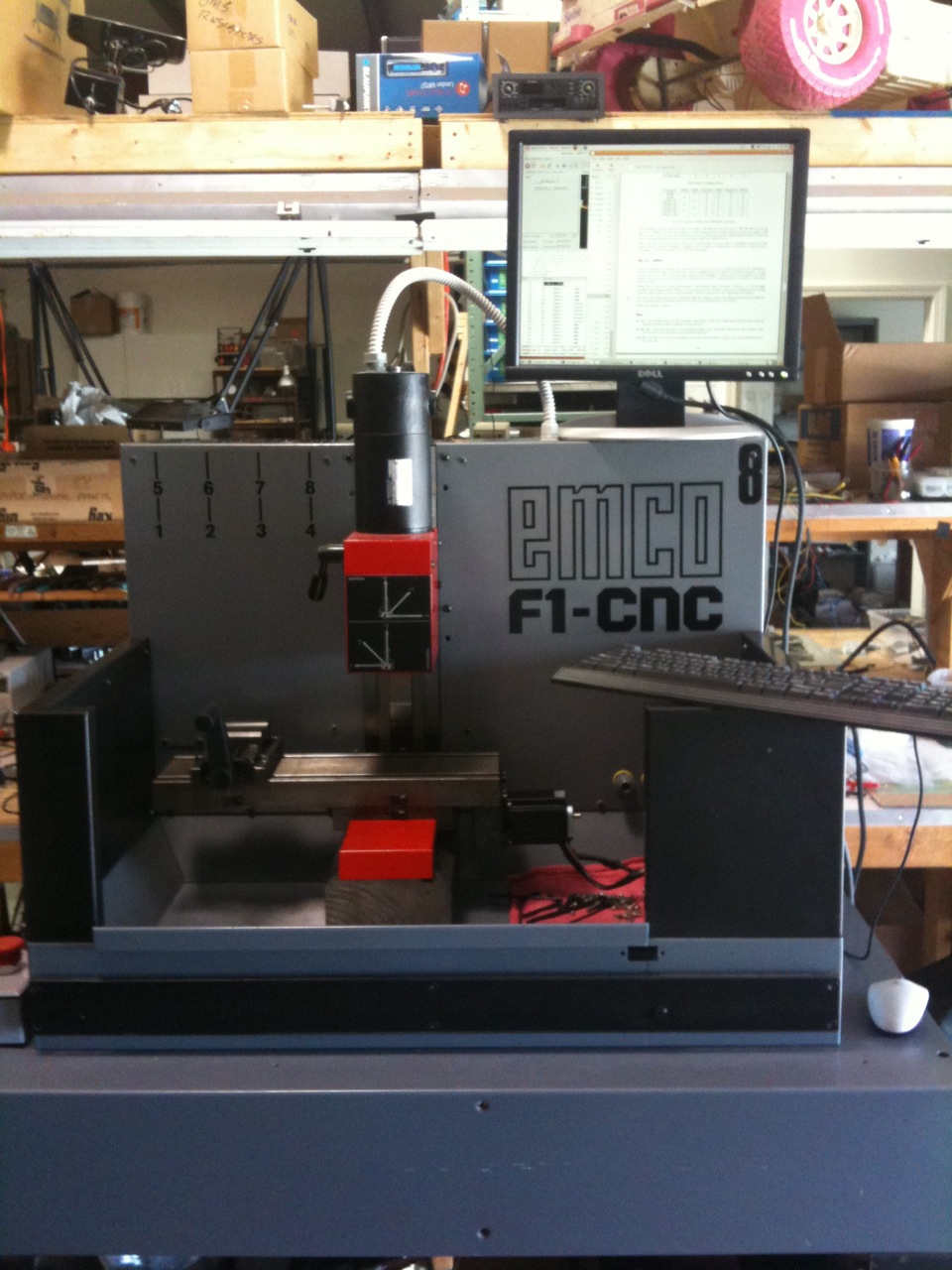
[16:51:26] <awallin_> grommit: any pics of your machine online? what is it?
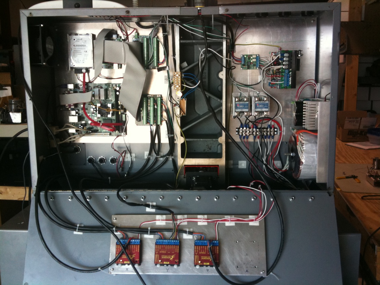
[16:51:36] <grommit> I will put some up for you
[16:51:59] <grommit> It is an EMCO F1, rebuilt. I put electronics in the back
[16:52:57] <grommit> http://bgp.nu/~tom/pub/IMG_1120.jpg
[16:53:11] <grommit> http://bgp.nu/~tom/pub/IMG_1128.jpg
[16:53:19] <awallin_> oh, there was one for sale here in finland just recently...
[16:53:40] <grommit> It is an Austrian made machine, often used at universities
[16:56:34] <awallin_> hm the one on sale is "Terco 3400"
[16:56:40] <awallin_> but looks quite similar
[16:57:37] <grommit> not familiar with that (terco)
[16:58:03] <awallin_> http://img.youtube.com/vi/zcda_gUy5zU/1.jpg
[16:59:06] <awallin_> http://www.youtube.com/watch?v=U0lwdsyeJ-o
[16:59:13] <grommit> That is a tiny picture :-)
[17:00:32] <awallin_> x285mm y135mm is not too big movements...
[17:00:54] <grommit> There are some similarities...
[17:01:54] <grommit> :-) the EMCO will only do 203mmX203mmX100mm
[17:02:16] <grommit> Have to start somewhere! ;-)
[17:02:34] <sealive> i did a PCB only 165x165x55mm
[17:02:40] <sealive> at 1200mm/min
[17:02:51] <sealive> pcb milling precise and fast
[17:03:10] <grommit> on an F1?
[17:03:37] <sealive> on a steper EMC
[17:04:23] <sealive> http://www.sammellothar.de/X_rahmen.mpg simulation
[17:04:56] <sealive> i can go downstäirs and shout a real picture if you want waiting for the alu table
[17:05:08] <sealive> there is only a wooden on the real
[17:05:44] <grommit> cool animation
[17:06:53] <sealive> the stepper of Z and Y are coliding
[17:07:37] <sealive> so i had to cange a litel the position of the Y and get a larger blet
[17:16:13] <sealive> http://www.pictureupload.de/originals/pictures/230410191602_minicnc2010.JPG
[17:16:23] <sealive> real picture of the minicnc
[17:16:56] <MrSunshine_> oo nice =)
[17:17:04] <MrSunshine_> its something like that im planing to build
[17:17:10] <MrSunshine_> for eurocard size pcb milling =)
[17:17:11] <grommit> nice
[17:17:16] <grommit> all homemade?
[17:17:25] <sealive> jes
[17:17:43] <sealive> also the Electronic
[17:17:59] <sealive> ok it wars a kit the L297/298
[17:18:15] <sealive> one moment i upload a picture of the driver
[17:18:20] <MrSunshine_> sealive, that mount for the milling head, can you realy tighten that up so that it grips something without tearing the threads out of the aluminium ?
[17:19:03] <sealive> yes no problem so far
[17:19:26] <MrSunshine_> well i guess alu is a bit flexible but i didnt think it whas THAT flexible =)
[17:19:33] <sealive> it mills it self for the pcb cart to the relay for the in and out M2M5
[17:19:47] <sealive> only 8mm
[17:20:14] <sealive> only 8mm thick and a M6 1/4" in it
[17:20:19] <MrSunshine_> a damn nice little thing =)
[17:20:26] <MrSunshine_> i want it =)
[17:21:48] <sealive> http://www.pictureupload.de/originals/pictures/230410192135_mini_l298.JPG
[17:21:59] <sealive> elektronics
[17:22:18] <sealive> as you see all axis are ballbeart with 12x3TR
[17:23:35] <MrSunshine_> but using L298 etc stuff
[17:23:37] <MrSunshine_> i dont get it
[17:23:40] <MrSunshine_> thats just half steps isnt it? :)
[17:23:49] <MrSunshine_> i just bought drivers that can go 256 micros! :P
[17:23:58] <MrSunshine_> tho maybe a bit more expensive :P
[17:24:02] <sealive> so i coudt not go to full speed at the larger version its 1800mm/min here it not reatches that amount only 1200 then its getting down cause of not enopg way
[17:24:44] <sealive> just calculate 3mm /800Steps per U
[17:24:56] <MrSunshine_> per U ? :P
[17:25:14] <sealive> 0,00375mm per step
[17:25:22] <sealive> U rpm
[17:25:32] <sealive> 1full turn
[17:26:02] <MrSunshine_> 800 steps ?
[17:26:12] <MrSunshine_> how do you figure that with half steps?
[17:26:19] <sealive> 400 the stepper half its 800
[17:26:34] <MrSunshine_> sealive, where the hell do you find 400 step/turn steppers? :)
[17:26:45] <sealive> China
[17:27:00] <MrSunshine_> never seen anything more then 200
[17:27:18] <sealive> even if you go 200real so 400 half its lower then 1/100mm
[17:27:46] <MrSunshine_> sealive, true =)
[17:27:48] <MrSunshine_> i guess
[17:27:51] <sealive> i did not need this ever an pcb or figure milling
[17:28:17] <MrSunshine_> but you could have 0.001875 :P
[17:28:23] <sealive> 3mm per turn of the Tread
[17:28:46] <MrSunshine_> or 0.0009375 :P
[17:28:57] <sealive> how wants that in real
[17:28:58] <MrSunshine_> at 16 microsteps :P
[17:29:13] <sealive> Show is not for actual milling
[17:29:35] <sealive> if i got Thead with 10mm
[17:29:40] <sealive> then ok
[17:29:46] <sealive> but not in homemaking
[17:30:08] <sealive> lower then 1/10 is good
[17:30:37] <MrSunshine_> hopefully i will getthere with my metal mill soon =)
[17:30:51] <MrSunshine_> building control box atm, then im on to remaking motor mounts etc to have ball bearings
[17:31:03] <MrSunshine_> and maybe finaly get rid of most off center issues etc of the screws
[17:31:11] <MrSunshine_> realy soon i get myself a belt drive
[17:31:23] <MrSunshine_> so i never have to do aligning of motors again :P
[17:31:25] <sealive> i got 4 Haas Vf-2 and 12 Minimill so no problem to that
[17:33:14] <sealive> if you want to do real milling go and by a real mashine otherwise its far good for the thing it has to do
[17:34:45] <MrSunshine_> sealive, im converting a sieg x1 mill =)
[17:34:49] <MrSunshine_> so its a "real" mill :P
[17:34:54] <MrSunshine_> tho it has to be rigidized some
[17:35:14] <sealive> the hole mashine including labtop and driver and all stuff fits into a box 12"x12"x14"
[17:36:04] <sealive> you coudt barly belive that there is a sutch fust milling mashine inside
[17:48:13] <MattyMatt> MattyMatt is now known as MattyMattle
[17:49:24] <grommit> How can I tune or determine setting for my spindle motor? I have an error about maxvel being too big for step timings and am also wondering what MAX-VELOCITY, MAX_ACCELERATION and SCALE should be set to. If I command anything over about S100 the spindle speeds up to some max (which I think is below 4000rpm max). Also, when I slow down, to say S50, the spindle nearly stops and then goes to the lower speed.
[17:49:42] <MattyMattle> MattyMattle is now known as MattyMatt
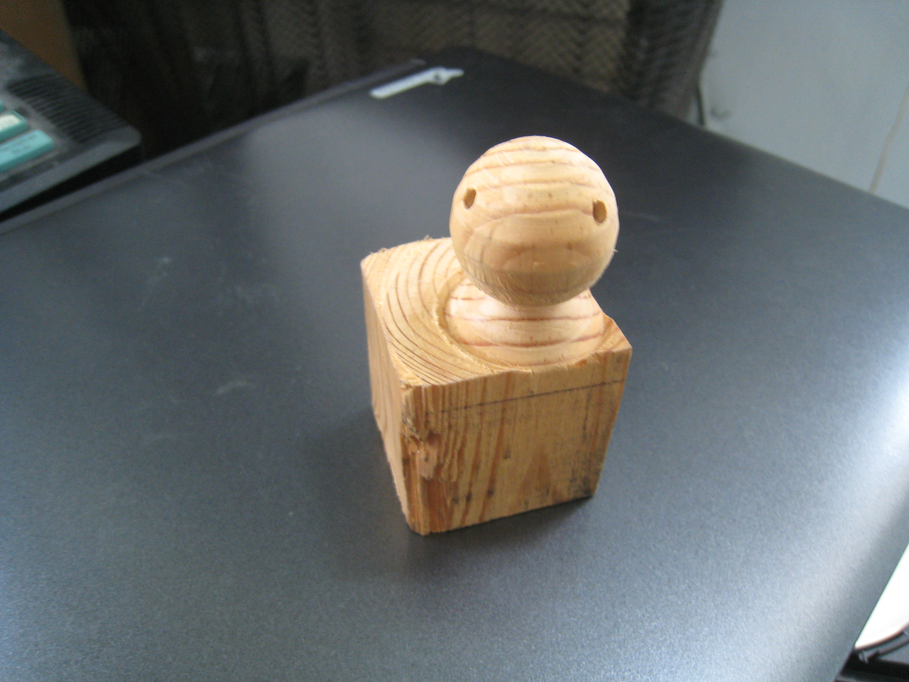
[18:10:20] <elmo401> frallzor: is the S.N. of that spindle 000007 ? ;)
[18:12:55] <frallzor> yup
[18:13:49] <skunkworks_> wow - that looks scary.
http://www.youtube.com/watch?v=CowMlr9F96I&feature=related
[18:14:07] <skunkworks_> * skunkworks_ hugs his realtime
[18:14:07] <SWPadnos> grommit, you should set the scale parameters so they make some sense
[18:15:02] <SWPadnos> I think the motion controller output you're using is in RPM, so you may want to scale the stepgen so that an input of 1 = 1 RPM (if possible)
[18:15:29] <SWPadnos> that probably means you take 25 kHz and divide by the max spindle speed at 10V input to the VFD
[18:16:24] <SWPadnos> (so a 3000 RPM spindle would have a scale of 25000/3000 = 8.333 steps/sec per RPM)
[18:17:06] <SWPadnos> then, you can set the max accel in RPM/second (not a normal unit), and maxvel in RPM
[18:34:30] <andypugh> Many potential bargains here:
http://www.ppauctions.com/ONLINE/index.php?a=1005&b=591&page=1&c=
[18:37:55] <cradek> wow, a bunch of renishaw stuff
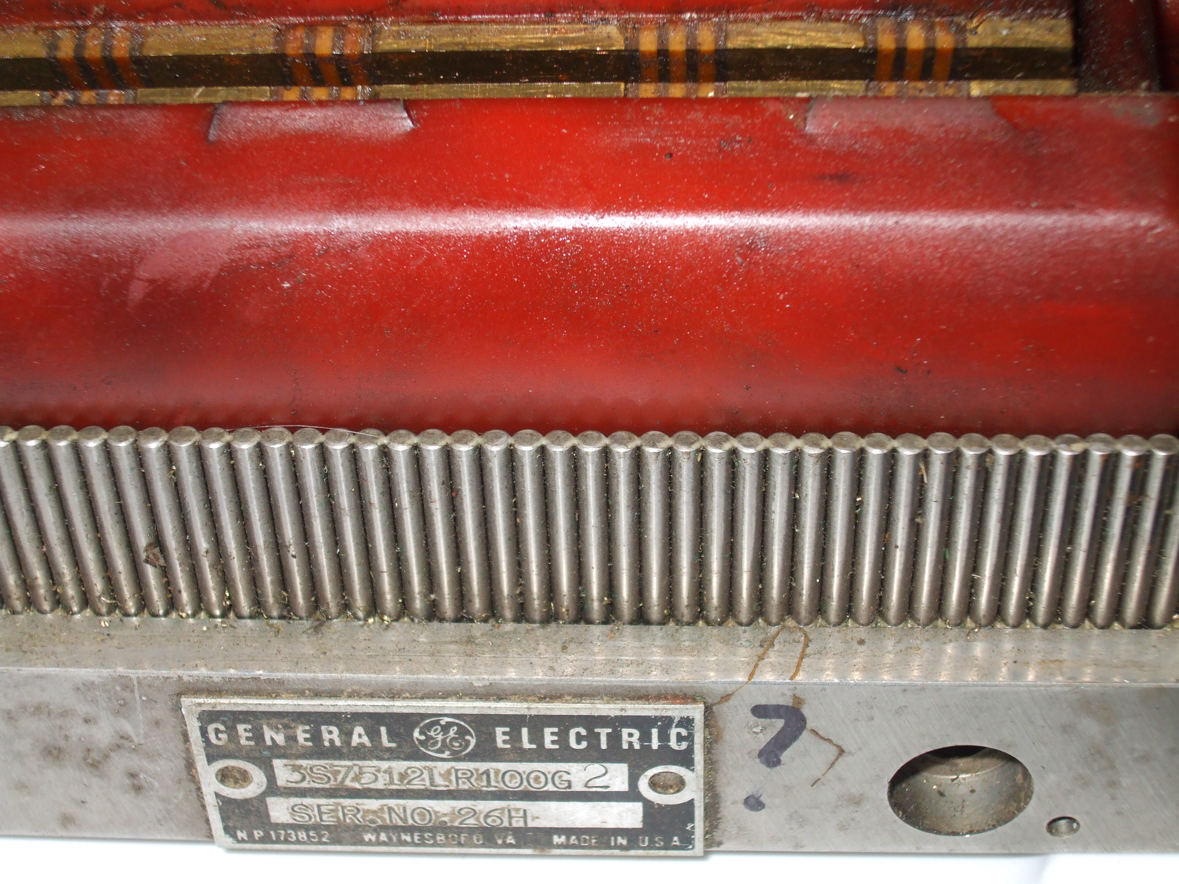
[18:39:44] <skunkworks_> cradek:
http://electronicsam.com/images/chris5axis.jpg recognize it? ;)
[18:41:59] <cradek> yeah, looks familiar
[18:42:06] <cradek> looks like the one I have, but with added holes
[18:42:51] <andypugh> Darn, I was hoping nobody had noticed that.
[18:42:58] <andypugh> (Renishaw, that is)
[18:43:31] <andypugh> I have a backup plan, I persuaded my semi-GF to apply for a job at Renishaw.
[19:07:32] <ds3> has anyone cut thin, one side textured ABS before?
[19:09:29] <andypugh> Only when cutting connector holes in instument boxes, I don't think it counts.
[19:11:56] <ds3> not quite.
[19:12:09] <ds3> want to figure out if I have a process problem or if that stuff just warps like mad
[19:22:28] <skunkworks_> I have only lasercut .125" abs - don't remember having a problem with warping...
[19:25:03] <andypugh> The Glass Transition Temperature is 100C (212F). If you go above that locally I think that you might have problems. But I just barely remember what Tg means, and had to look up the actual number.
[19:30:02] <ds3> skunkworks_: was it smooth or textured on one side?
[19:30:38] <ds3> andypugh: this is with a laser so definitely above that
[19:31:25] <alex_joni> http://adsoftheworld.com/files/images/Boss.jpg
[19:31:25] <andypugh> I have been reading a bit more about it, and I think Tg might be a red herring.
[19:32:10] <ds3> I suppose I could find more stock and see what happens if I cut it the other way
[19:32:14] <andypugh> I was thinking that it was a phase change with a volume change (like steel at the ferrite-austenite transition) but I don't think it is.
[19:32:25] <ds3> Hmmm
[19:33:13] <andypugh> Can you cut some cold (with shears maybe) and see if it still warps? If so then it is residual stress.
[19:33:37] <andypugh> The fact that Tg is 100 degrees seems to indicate that you can smooth it with a steam iron, if required.
[19:33:44] <ds3> I have torn off small peices and that didn't warp by itself
[19:34:00] <ds3> SHears always curl things for me , even sheet metal
[19:34:24] <andypugh> Yeah, you might have to use a guillotine.
[19:34:42] <ds3> no access to one at the moment
[19:34:43] <andypugh> And if you don't have one it isn't worth looking for one for the experiment.
[19:35:52] <ds3> *nod*
[19:36:15] <ds3> I could get more materials and try cutting it on the mill
[19:36:32] <ds3> only problem is I have to redo the g-code (too lazy to write it with G43/G42)
[19:38:11] <skunkworks_> halinput works - right?
[19:38:23] <skunkworks_> hal_input
[19:39:11] <andypugh> Is that what we use for joypads?
[19:39:16] <skunkworks_> I don't understand - if this is a normal usb device.. he cannot run the led's
http://cnczone.com/forums/showthread.php?t=103639
[19:39:36] <skunkworks_> according to this...
http://linuxcnc.org/docs/2.3/html/man/man1/hal_input.1.html
[19:39:44] <skunkworks_> it creates pins for inputs and outputs.
[19:39:54] <skunkworks_> * skunkworks_ hasn't used it.
[19:40:50] <SWPadnos> uh. why wouldn't he be able to use the LEDs?
[19:41:12] <skunkworks_> that is what I am asking. ;)
[19:41:36] <SWPadnos> sure he can, if he has an input-compliant device that exports LED functions
[19:41:45] <SWPadnos> same way you can control keyboard LEDs
[19:42:31] <andypugh> He might want to look at Frank(?)'s HID-comp instead if it doesn't work with HAL-input
[19:42:32] <SWPadnos> maybe he's using the HID driver, not hal_input
[19:42:40] <SWPadnos> I don't know if that one supports LED outputs
[19:42:57] <andypugh> There is Generic-HID too.
[19:43:12] <andypugh> (And no, I don't know if that does either)
[19:43:18] <SWPadnos> hal_input should work with any HID device that the Linux input layer recognizes
[19:43:38] <SWPadnos> but I don't know if the other HID-only drivers export pins for LEDs
[19:43:41] <skunkworks_> I will ask.. :)
[19:43:46] <andypugh> Just in front of me behind the keyboard I have a USB HID chip on a breadboard, but that project got no further.
[19:49:45] <frallzor> I got 16mm scrapwood of MDF, what to make with it? =)
[19:56:55] <andypugh> A casting pattern for your 4th and 5th axis mounts.
[19:59:00] <frallzor> cant fit that :P
[20:02:53] <frallzor> a coat rack maybe
[20:05:37] <andypugh> Grr, there is a semi-bug in the Arduino terminal. If you forget to println rather than print and are running a fast thread, it seems to freeze the serial terminal and hence the whole app.
[21:07:03] <Guest285> hi all , haw to get wit the git the 2.4 version
[21:11:12] <andypugh> http://wiki.linuxcnc.org/emcinfo.pl?Git]
[21:11:19] <andypugh> http://wiki.linuxcnc.org/emcinfo.pl?Git
[21:11:32] <andypugh> I mean. I hit one key too many
[21:13:03] <Guest285> thanks
[22:09:44] <andypugh> My servo motor rotates unexpectedly slowly, and sets a drive fault after a few tens of revolutions. I wonder what could be wrong?
[22:11:12] <andypugh> (Other than the fact that the motor is a totally different type to what the drive is meant for, as the drive is a 24V 5A BLDC drive with Hall inputs, and the motor is a 300V 7.5A AC servo with a Resolver.)
[22:13:39] <MarkusBec> MarkusBec is now known as MarkusBec_away
[22:26:14] <MarkusBec_away> MarkusBec_away is now known as MarkusBec
[22:59:42] <DaViruz> no specifics on the drive fault?
[23:14:11] <frallzor> oh DaViruz lives!
[23:14:36] <DaViruz> andypugh: no specifics on the drive failt?
[23:14:37] <DaViruz> fault
[23:14:53] <andypugh> Just a red LED.
[23:15:15] <andypugh> Considering everything, it is a marvel that the motor rotates at all.
[23:24:50] <andypugh> I have just realised something else I could try.
[23:26:10] <andypugh> The drives are Bodine, and have a rather odd commutation pattern that only suits Bodine motors. I have modified two of the drives to run a standard pattern, but one is unmodified. As my Hall-pattern is entirely governed by software, I can recreate the Bodine pattern and see if that works better.
[23:27:10] <andypugh> (Though I am not at all sure how you find the rotor position that corresponds to commutation pattern 1)
[23:28:59] <MarkusBec> MarkusBec is now known as MarkusBec_away