Conventions used in this section
In the G Code prototypes the hyphen (-) stands for a real value.
A real value may be:
-
An explicit number, 4
-
An expression, [2+2]
-
A parameter value, #88
-
A unary function value, acos[0]
In most cases, if axis words are given (any or all of XYZABCUVW), they specify a destination point.
Axis numbers are in the currently active coordinate system, unless explicitly described as being in the absolute coordinate system. Where axis words are optional, any omitted axes will have their current value.
Any items in the G Code prototypes not explicitly described as optional are required.
The values following letters are often given as explicit numbers. Unless stated otherwise, the explicit numbers can be real values. For example, G10 L2 could equally well be written G[2*5] L[1+1]. If the value of parameter 100 were 2, G10 L#100 would also mean the same.
If L- is written in a prototype the - will often be referred to as the "L number", and so on for any other letter.
1. Polar Coordinates
Polar Coordinates can be used to specify the XY coordinate of a move. The @n is the distance and ^n is the angle. The advantage of this is for things like bolt hole circles which can be done very simply by moving to a point in the center of the circle, setting the offset and then moving out to the first hole then run the drill cycle. Polar Coordinates always are from the current XY zero position. To shift the Polar Coordinates from machine zero use an offset or select a coordinate system.
In Absolute Mode the distance and angle is from the XY zero position and the angle starts with 0 on the X Positive axis and increases in a CCW direction about the Z axis. The code G1 @1^90 is the same as G1 Y1.
In Relative Mode the distance and angle is also from the XY zero position but it is cumulative. This can be confusing at first how this works in incremental mode.
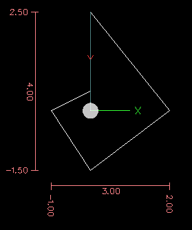
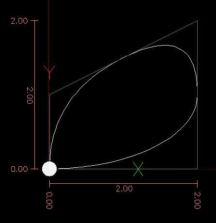
For example if you have the following program you might expect it to be a square pattern.
F100 G1 @.5 ^90
G91 @.5 ^90
@.5 ^90
@.5 ^90
@.5 ^90
G90 G0 X0 Y0 M2
You can see from the following figure that the output is not what you might expect. Because we added 0.5 to the distance each time the distance from the XY zero position increased with each line.
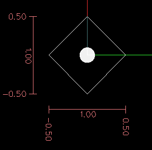
The following code will produce our square pattern.
F100 G1 @.5 ^90
G91 ^90
^90
^90
^90
G90 G0 X0 Y0 M2
As you can see by only adding to the angle by 90 degrees each time the end point distance is the same for each line.
It is an error if:
-
An incremental move is started at the origin
-
A mix of Polar and and X or Y words are used
2. Quick Reference Table
| Code | Description | Section |
|---|---|---|
G0 |
Coordinated Straight Motion Rapid |
|
G1 |
Coordinated Straight Motion Feed Rate |
|
G2, G3 |
Coordinated Helical Motion Feed Rate |
|
G4 |
Dwell |
|
G5.1 |
Quadratic B-Spline |
|
G5.2, G5.3 |
NURBs Block |
|
G7 |
Diameter Mode (lathe) |
|
G8 |
Radius Mode (lathe) |
|
G10 L1 |
Set Tool Table Entry |
|
G10 L10 |
Set Tool Table, Calculated, Workpiece |
|
G10 L11 |
Set Tool Table, Calculated, Fixture |
|
G10 L2 |
Coordinate System Origin Setting |
|
G10 L20 |
Coordinate System Origin Setting Calculated |
|
G17 - G19.1 |
Plane Select |
|
G20, G21 |
Units of Measure |
|
G28 - G28.1 |
Go to Predefined Position |
|
G30 - G30.1 |
Go to Predefined Position |
|
G33 |
Spindle Synchronized Motion |
|
G33.1 |
Rigid Tapping |
|
G38.2 - G38.5 |
Probing |
|
G40 |
Cancel Cutter Compensation |
|
G41, G42 |
Cutter Compensation |
|
G41.1, G42.1 |
Cutter Compensation Transient |
|
G43, G43.1 |
Use Tool Length Offset from Tool Table |
|
G49 |
Cancel Tool Length Offset |
|
G53 |
Motion in Machine Coordinate System |
|
G54-G59 |
Select Coordinate System (1 - 6) |
|
G59.1-G59.3 |
Select Coordinate System (7 - 9) |
|
G61, G61.1 |
Path Control Mode |
|
G64 |
Path Control Mode with Optional Tolerance |
|
G73 |
Drilling Cycle with Chip Breaking |
|
G76 |
Multipass Threading Cycle (Lathe) |
|
G80 |
Cancel Motion Modes |
|
G81 |
Drilling Cycle |
|
G82 |
Drilling Cycle with Dwell |
|
G83 |
Drilling Cycle with Peck |
|
G84 |
Right Hand Tapping Cycle (unimplemented) |
|
G85 |
Boring Cycle, No Dwell, Feed Out |
|
G86 |
Boring Cycle, Stop, Rapid Out |
|
G87 |
Back-Boring Cycle (unimplemented) |
|
G88 |
Boring Cycle, Stop, Manl Out (unimplemented) |
|
G89 |
Boring Cycle, Dwell, Feed Out |
|
G90, G91 |
Distance Mode |
|
G90.1, G91.1 |
Arc Distance Mode |
|
G92 |
Offset Coordinate Systems & Set Parameters |
|
G92.1 |
Cancel Offsets |
|
G92.2 |
Cancel Offsets |
|
G92.3 |
Apply Parameters to Offset Coordinate Systems |
|
G93, G94, G95 |
Feed Modes |
|
G96 |
Constant Surface Speed |
|
G97 |
RPM Mode |
|
G98, G99 |
Canned Cycle Z Retract Mode |
| Code | Description | Section |
|---|---|---|
M0, M1, M2 |
Program Control |
|
M3, M4, M5 |
Spindle Control |
|
M6 |
Tool Change |
|
M7, M8, M9 |
Coolant Control |
|
M30, M60 |
Pallet Shuttle |
|
M48 |
Override Controls |
|
M49 |
Override Controls |
|
M50 |
Override Controls |
|
M51 |
Override Controls |
|
M52 |
Override Controls |
|
M53 |
Override Controls |
|
M61 |
Set Current Tool Number |
|
M62-65 |
Output Control |
|
M66 |
Input Control |
|
M67 |
Analog Output Control |
|
M68 |
Analog Output Control |
|
M100-M199 |
User Defined M-Codes |
|
O |
O Codes |
|
F |
Feed |
|
S |
Spindle Speed |
|
T |
Tool Select |
3. G0 Rapid Motion
G0 axes
For rapid linear (straight line) motion, program G0 'axes', where all the axis words are optional. The G0 is optional if the current motion mode is G0. This will produce coordinated linear motion to the destination point at the current traverse rate (or slower if the machine will not go that fast). It is expected that cutting will not take place when a G0 command is executing.
If cutter radius compensation is active, the motion will differ from the above; see Section [sec:Cutter-Radius-Compensation].
If G53 is programmed on the same line, the motion will also differ; see Section [sub:G53-Move-in].
It is an error if:
-
An axis letter is without a real value.
4. G1 Linear Motion
G1 axes
For linear (straight line) motion at programed feed rate (for cutting or not), program G1 'axes', where all the axis words are optional. The G1 is optional if the current motion mode is G1 . This will produce coordinated linear motion to the destination point at the current feed rate (or slower if the machine will not go that fast).
If cutter radius compensation is active, the motion will differ from the above; see Section [sec:Cutter-Radius-Compensation].
If G53 is programmed on the same line, the motion will also differ; see Section [sub:G53-Move-in].
It is an error if:
-
No feed rate has been set.
5. G2, G3 Arc
A circular or helical arc is specified using either G2 (clockwise arc) or G3 (counterclockwise arc). The direction (CW, CCW) is as viewed from the positive end of the axis about which the circular motion occurs.
The axis of the circle or helix must be parallel to the X, Y, or Z axis of the machine coordinate system. The axis (or, equivalently, the plane perpendicular to the axis) is selected with G17 (Z-axis, XY-plane), G18 (Y-axis, XZ-plane), or G19 (X-axis, YZ-plane). Planes 17.1, 18.1, and 19.1 are not currently supported. If the arc is circular, it lies in a plane parallel to the selected plane.
To program a helix, include the axis word perpendicular to the arc plane: for example, if in the G17 plane, include a Z word. This will cause the Z axis to move to the programmed value during the circular XY motion.
To program an arc that gives more than one full turn, use a P word specifying the number of full or partial turns of arc. If P is unspecified, the behavior is as if P1 was given: that is, only one full or partial turn will result, giving an arc less than or equal to one full circle. For example, if an arc is programmed with P2, the resulting motion will be more than one full circle and up to two full circles (depending on the programmed endpoint.) Multiturn helical arcs are supported and give motion useful for milling holes or threads.
If a line of code makes an arc and includes rotary axis motion, the rotary axes turn at a constant rate so that the rotary motion starts and finishes when the XYZ motion starts and finishes. Lines of this sort are hardly ever programmed.
If cutter radius compensation is active, the motion will differ from what is described here. See Section [sec:Cutter-Radius-Compensation].
Two formats are allowed for specifying an arc: Center Format and Radius Format.
It is an error if:
-
No feed rate has been set.
5.1. Center format arcs (preferred format)
In the center format, the coordinates of the end point of the arc in the selected plane are specified along with the offsets of the center of the arc from the current location. In this format, it is OK if the end point of the arc is the same as the current point.
It is an error if:
-
When the arc is projected on the selected plane, the distance from the current point to the center differs from the distance from the end point to the center by more than 0.0002 inch (if inches are being used) or 0.002 millimeter (if millimeters are being used).
When the XY-plane is selected program:
G2 or G3 axes I- J-
The axis words are all optional except that at least one of X and Y must be used to program an arc of less than 360 degrees. I and J are the offsets from the current location (in the X and Y directions, respectively) of the center of the circle. I and J are optional except that at least one of the two must be used. If only one is specified, the value of the other is taken as 0. If you include the Z word it will helix.
It is an error if:
-
I and J are both omitted.
When the XZ-plane is selected program:
G2 or G3 axes I- K-
The axis words are all optional except that at least one of X and Z must be used to program an arc of less than 360 degrees. I and K are the offsets from the current location (in the X and Z directions, respectively) of the center of the circle. I and K are optional except that at least one of the two must be used. If only one is specified, the value of the other is taken as 0. In Diameter Mode G7 I & K are still radius dimensions.
It is an error if:
-
I and K are both omitted.
When the YZ-plane is selected program:
G2 or G3 axes J- K-
The axis words are all optional except that at least one of Y and Z must be used to program an arc of less than 360 degrees. J and K are the offsets from the current location (in the Y and Z directions, respectively) of the center of the circle. J and K are optional except that at least one of the two must be used. If only one is specified, the value of the other is taken as 0.
It is an error if:
-
J and K are both omitted.
5.2. Examples
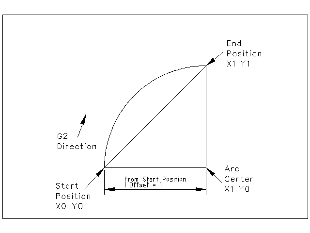
Calculating arcs by hand can be difficult at times. One option is to draw the arc with a cad program to get the coordinates and offsets. Keep in mind the tolerance mentioned above, you may have to change the precision of your cad program to get the desired results. Another option is to calculate the coordinates and offset using formulas. As you can see in the following figures a triangle can be formed from the current position the end position and the arc center.
In the following figure you can see the start position is X0 Y0, the end position is X1 Y1. The arc center position is at X1 Y0. This gives us an offset from the start position of 1 in the X axis and 0 in the Y axis. In this case only an I offset is needed.
The code for the example:
G2 X1 Y1 I1 F10
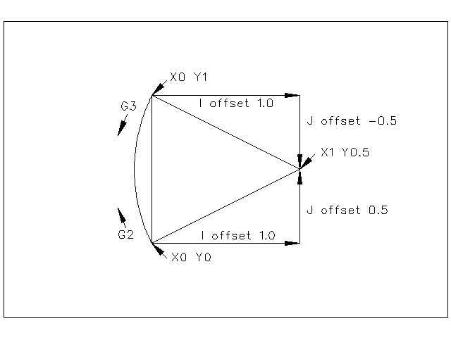
In the next example we see the difference between the offsets for Y if we are doing a G2 or a G3 move. For the G2 move the start position is X0 Y0, for the G3 move it is X0 Y1. The arc center is at X1 Y0.5 for both moves. The G2 move the J offset is 0.5 and the G3 move the J offset is -0.5.
The g code for the following example:
G2 X0 Y1 I1 J0.5 F25
G3 X0 Y0 I1 J-0.5 F25
Here is an example of a center format command to mill a helix:
G17 G2 X10 Y16 I3 J4 Z9
That means to make a clockwise (as viewed from the positive z-axis) circular or helical arc whose axis is parallel to the Z-axis, ending where X=10, Y=16, and Z=9, with its center offset in the X direction by 3 units from the current X location and offset in the Y direction by 4 units from the current Y location. If the current location has X=7, Y=7 at the outset, the center will be at X=10, Y=11. If the starting value of Z is 9, this is a circular arc; otherwise it is a helical arc. The radius of this arc would be 5.
In the center format, the radius of the arc is not specified, but it may be found easily as the distance from the center of the circle to either the current point or the end point of the arc.
5.3. Full Circles
G2 or G3 I- J- K-
To do a full 360 circle from the current location only program the I, J or K offset from the current location for the G2/G3. To program a 360 degree helix in the XY plane just include the Z word.
It is an error if:
-
The K offset is used in the XY plane
-
The J offset is used in the XZ plane
-
the I offset is used in the YZ plane
5.4. Radius format arcs (discouraged format)
In the radius format, the coordinates of the end point of the arc in the selected plane are specified along with the radius of the arc. Program G2 axes R- (or use G3 instead of G2 ). R is the radius. The axis words are all optional except that at least one of the two words for the axes in the selected plane must be used. The R number is the radius. A positive radius indicates that the arc turns through less than 180 degrees, while a negative radius indicates a turn of more than 180 degrees. If the arc is helical, the value of the end point of the arc on the coordinate axis parallel to the axis of the helix is also specified.
It is an error if:
-
both of the axis words for the axes of the selected plane are omitted
-
the end point of the arc is the same as the current point.
It is not good practice to program radius format arcs that are nearly full circles or nearly semicircles because a small change in the location of the end point will produce a much larger change in the location of the center of the circle (and, hence, the middle of the arc). The magnification effect is large enough that rounding error in a number can produce out-of-tolerance cuts. For instance, a 1% displacement of the endpoint of a 180 degree arc produced a 7% displacement of the point 90 degrees along the arc. Nearly full circles are even worse. Other size arcs (in the range tiny to 165 degrees or 195 to 345 degrees) are OK.
Here is an example of a radius format command to mill an arc:
G17 G2 X10 Y15 R20 Z5
That means to make a clockwise (as viewed from the positive Z-axis) circular or helical arc whose axis is parallel to the Z-axis, ending where X=10, Y=15, and Z=5, with a radius of 20. If the starting value of Z is 5, this is an arc of a circle parallel to the XY-plane; otherwise it is a helical arc.
6. G4 Dwell
G4 P[seconds]
For a dwell, program G4 P- . This will keep the axes unmoving for the period of time in seconds specified by the P number.
It is an error if:
-
the P number is negative.
7. G5.1 Quadratic B-spline
G5.1 Xn Yn I[X offset] J[Y offset]
G5.1 creates a quadratic B-spline in the XY plane with the X and Y axis only.
It is an error if:
-
I and J offset is not specified
-
An axis other than X or Y is specified
-
The active plane is not G17
8. G5.2 G5.3 NURBs Block
Warning: G5.2, G5.3 is experimental and not fully tested.
G5.2 is for opening the data block defining a NURBs and G5.3 for closing the data block. In the lines between these two codes the curve control points are defined with both their related "weights" (P) and their parameter (L) which determines the order of the curve (k) and subsequently its degree (k-1).
Using this curve definition the knots of the NURBs curve are not defined by the user they are calculated by the inside algorithm, in the same way as it happens in a great number of graphic applications, where the curve shape can be modified only acting on either control points or weights.
Sample NURBs Code
    G0 X0 Y0
    F10
    G5.2 X0 Y1 P1 L3
         X2 Y2 P1
         X2 Y0 P1
         X0 Y0 P2
    G5.3
    / The rapid moves show the same path without the NURBs Block
    G0 X0 Y1
       X2 Y2
       X2 Y0
       X0 Y0
    M2
More information on NURBs can be found here:
9. G7 Diameter Mode
Program G7 to enter the diameter mode for axis X on a lathe. When in the Diameter mode the X axis moves on a lathe will be 1/2 the distance to the center of the lathe. For example X1 would move the cutter to 0.500” from the center of the lathe thus giving a 1” diameter part.
10. G8 Radius Mode
Program G8 to enter the radius mode for axis X on a lathe. When in Radius mode the X axis moves on a lathe will be the distance from the center. Thus a cut at X1 would result in a part that is 2" in diameter. G8 is default at power up.
11. G10 L1 Set Tool Table
G10 L1 P[tool number] R[radius]
    X[offset] Y[offset] Z[offset]
    A[offset] B[offset] C[offset]
    U[offset] V[offset] W[offset]
    I[frontangle] J[backangle] Q[orientation]
Program a G10 L1 to set a tool table entry from a program or the MDI window. A valid G10 L1 rewrites the tool table.
It is an error if:
-
Cutter Compensation is on
-
The P number is unspecified
For more information on cutter orientation, see the [cap:Lathe-Tool-Orientations] diagram.
12. G10 L2 Set Coordinate System
G10 L2 P[coordinate system] R[XY rotation about Z]
    X[offset] Y[offset] Z[offset]
    A[offset] B[offset] C[offset]
    U[offset] V[offset] W[offset]
The coordinate system is described in Section [cha:Coordinate-System].
To set the origin of a coordinate system, program G10 L2 P- R- axes, where the P number is in the range 0 to 9. For the currently active coordinate system program P0. To specify a coordinate system program 1 to 9 corresponding to G54 to G59.3. Optionally program R to indicate the rotation of the XY axis around the Z axis. All axis words are optional. The origin of the coordinate system specified by the P number is set to the given values (in terms of the not offset machine coordinate system). Only those coordinates for which an axis word is included on the line will be set. Being in incremental distance mode (G91) has no effect on G10 L2. The direction of rotation is CCW as viewed from the Top View.
Important Concepts:
-
G10 L2 Pn does not change from the current coordinate system to the one specified by P, you have to use G54-59.3 to select a coordinate system.
-
When a rotation is in effect jogging an axis will only move that axis in a positive or negative direction and not along the rotated axis.
It is an error if:
-
The P number does not evaluate to an integer in the range 0 to 9.
-
An axis is programmed that is not defined in the configuration.
If a G92 origin offset was in effect before G10 L2, it will continue to be in effect afterwards.
The coordinate system whose origin is set by a G10 command may be active or inactive at the time the G10 is executed. If it is currently active, the new coordinates take effect immediately.
Examples:
- G10 L2 P1 X3.5 Y17.2
-
Sets the origin of the first coordinate system (the one selected by G54) to be X=3.5 and Y=17.2. Because only X and Y are specified, the origin point is only moved in X and Y; the other coordinates are not changed.
- G10 L2 P1 X0 Y0 Z0
-
Sets the XYZ coordinates of the G54 origin to the unoffset origin.
13. G10 L10 Set Tool Table
G10 L10 P[tool number] R[radius]
    X[set_curr_sys_to] Y[set_curr_sys_to] Z[set_curr_sys_to]
    A[set_curr_sys_to] B[set_curr_sys_to] C[set_curr_sys_to]
    U[set_curr_sys_to] V[set_curr_sys_to] W[set_curr_sys_to]
    I[frontangle] J[backangle] Q[orientation]
G10 L10 changes the tool table entry for tool P so that if the tool offset is reloaded, with the machine in its current position and with the current G5x and G92 offsets active, the current coordinates for the given axes will become the given values. The axes that are not specified in the G10 L10 command will not be changed.
It is an error if:
-
Cutter Compensation is on
14. G10 L11 Set Tool Table
G10 L11 P[tool number] R[radius]
    X[set_curr_loc_to] Y[set_curr_loc_to] Z[set_curr_loc_to]
    A[set_curr_loc_to] B[set_curr_loc_to] C[set_curr_loc_to]
    U[set_curr_loc_to] V[set_curr_loc_to] W[set_curr_loc_to]
    I[frontangle] J[backangle] Q[orientation]
G10 L11 is just like G10 L10 except that instead of setting the entry according to the current offsets, it is set so that the current coordinates would become the given value if the new tool offset is reloaded and the machine is placed in the G59.3 coordinate system without any G92 offset active.
This allows the user to set the G59.3 coordinate system according to a fixed point on the machine, and then use that fixture to measure tools without regard to other currently-active offsets.
It is an error if:
-
Cutter Compensation is on
15. G10 L20 Set Coordinate System
G10 L20 P[coordinate system] R[rotation about Z]
    X[set_curr_loc_to] Y[set_curr_loc_to] Z[set_curr_loc_to]
    A[set_curr_loc_to] B[set_curr_loc_to] C[set_curr_loc_to]
    U[set_curr_loc_to] V[set_curr_loc_to] W[set_curr_loc_to]
G10 L20 is similar to G10 L2 except that instead of setting the offset/entry to the given value, it is set to a calculated value that makes the current coordinates become the given value.
It is an error if:
-
The P number does not evaluate to an integer in the range 0 to 9.
-
An axis is programmed that is not defined in the configuration.
16. G17, G18, G19, G17.1, G18.1, G19.1 Plane Selection
These codes set the current plane as follows:
| G17 | XY (default) |
|---|---|
G18 |
ZX |
G19 |
YZ |
G17.1 |
UV |
G18.1 |
WU |
G19.1 |
VW |
The effects of having a plane selected are discussed in Section [sec:G2-G3-Arc] and Section [sec:G81-G89]
17. G20, G21 Length Units
Program G20 to use inches for length units.
Program G21 to use millimeters for length units.
It is usually a good idea to program either G20 or G21 near the beginning of a program before any motion occurs, and not to use either one anywhere else in the program.
18. G28, G28.1 Go to Predefined Position
G28 uses the values in parameters 5161-5166 as the absolute values to make a rapid traverse move to from the current position. The parameter values are in terms of the absolute coordinate system and the machine’s native coordinate system.
G28 axes will make a rapid traverse move to the position specified by axes, then will make a rapid traverse move to the predefined position in parameters 5161-5166.
G28.1 stores the current absolute position into parameters 5161-5166.
It is an error if :
-
Radius compensation is turned on
19. G30, G30.1 Go to Predefined Position
G30 uses the values in parameters 5181-5186 as the absolute values to make a rapid traverse move to from the current position. The parameter values are in terms of the absolute coordinate system and the machine’s native coordinate system.
G30 axes will make a rapid traverse move to the position specified by axes, then will make a rapid traverse move to the predefined position in parameters 5181-5186.
G30.1 stores the current absolute position into parameters 5181-5186.
G30 parameters will be used to move the tool when a M6 is programmed if [TOOL_CHANGE_AT_G30]=1 is in the [EMCIO] section of the ini file.
It is an error if :
-
Radius compensation is turned on
20. G33 Spindle-Synchronized Motion
G33 X- Y- Z- K-
For spindle-synchronized motion in one direction, code G33 X- Y- Z- K- where K gives the distance moved in XYZ for each revolution of the spindle. For instance, if starting at Z=0, G33 Z-1 K.0625 produces a 1 inch motion in Z over 16 revolutions of the spindle. This command might be part of a program to produce a 16TPI thread. Another example in metric, G33 Z-15 K1.5 produces a movement of 15mm while the spindle rotates 10 times for a thread of 1.5mm.
Note: K follows the drive line described by X- Y- Z- and is not parallel to the Z axis.
Spindle-synchronized motions wait for spindle index, so multiple passes line up. G33 moves end at the programmed endpoint.
All the axis words are optional, except that at least one must be used.
It is an error if:
-
All axis words are omitted.
-
The spindle is not turning when this command is executed
-
The requested linear motion exceeds machine velocity limits due to the spindle speed
21. G33.1 Rigid Tapping
G33.1 X- Y- Z- K-
For rigid tapping (spindle synchronized motion with return), code G33.1 X- Y- Z- K- where K- gives the distance moved for each revolution of the spindle. A rigid tapping move consists of the following sequence:
-
A move to the specified coordinate, synchronized with the spindle at the given ratio and starting with a spindle index pulse.
-
When reaching the endpoint, a command to reverse the spindle (e.g., from clockwise to counterclockwise).
-
Continued synchronized motion beyond the specified end coordinate until the spindle actually stops and reverses.
-
Continued synchronized motion back to the original coordinate.
-
When reaching the original coordinate, a command to reverse the spindle a second time (e.g., from counterclockwise to clockwise).
-
Continued synchronized motion beyond the original coordinate until the spindle actually stops and reverses.
-
An unsynchronized move back to the original coordinate.
Spindle-synchronized motions wait for spindle index, so multiple passes line up. G33.1 moves end at the original coordinate.
All the axis words are optional, except that at least one must be used.
It is an error if:
-
All axis words are omitted.
-
The spindle is not turning when this command is executed
-
The requested linear motion exceeds machine velocity limits due to the spindle speed
Example:
;move to starting position
G0 X1.000 Y1.000 Z0.100
;rigid tapping a 20 TPI thread
G33.1 Z-0.750 K0.05
22. G38.x Straight Probe
|
Important
|
You will not be able to successfully use this command until your machine has been set up to provide a probe signal via HAL to EMC2. The probe signal must be input via a HAL input bit, and then forwarded to motion.probe-input (bit, in). G38.x uses the value on this pin to determine when the probe has made (or lost) contact. TRUE for probe contact closed (touching), FALSE for probe contact open. |
Program G38.2 'axes', G38.3 'axes', G38.4 'axes', or G38.5 'axes' to perform a straight probe operation. The axis words are optional, except that at least one of them must be used. The axis words together define the destination point that the probe will move towards, starting from the current location. The tool in the spindle must be a probe.
It is an error if:
-
the current point is the same as the programmed point.
-
no axis word is used
-
cutter radius compensation is enabled
-
the feed rate is zero
-
the probe is already in the target state
In response to this command, the machine moves the controlled point (which should be at the center of the probe ball) in a straight line at the current feed rate toward the programmed point. In inverse time feed mode, the feed rate is such that the whole motion from the current point to the programmed point would take the specified time. The move stops (within machine acceleration limits) when the programmed point is reached, or when the requested change in the probe input takes place, whichever occurs first.
The table [cap:Probing-codes] shows the significance of different probing codes.
After successful probing, parameters 5061 to 5069 will be set to the coordinates of XYZABCUVW of the location of the controlled point at the time the probe changed state. After unsuccessful probing, they are set to the coordinates of the programmed point. Parameter 5070 is set to 1 if the probe succeeded and 0 if the probe failed. If the probing operation failed, G38.2 and G38.4 will signal an error by posting an message onscreen if the selected GUI supports that. (And by halting program execution? FIXME TODO )
A comment of the form (PROBEOPEN filename.txt) will open filename.txt and store the 9-number coordinate consisting of XYZABCUVW of each successful straight probe in it. The file must be closed with (PROBECLOSE).
23. G40 Compensation Off
Program G40 to turn cutter radius compensation off. The next move must be a straight move. It is OK to turn compensation off when it is already off.
It is an error if:
-
A G2/G3 arc move is programmed next after a G40.
24. G41, G42 Tool Radius Compensation
G41 or G42 D[tool]
To start tool radius compensation to the left of the part profile, use G41. G41 starts cutter radius compensation to the left of the programmed line as viewed from the positive end of the axis perpendicular to the plane.
To start tool radius compensation to the right of the part profile, use G42. G42 starts cutter radius compensation to the right of the programmed line as viewed from the positive end of the axis perpendicular to the plane.
The lead in move must be at least as long as the tool radius. The lead in move can be a rapid move.
Cutter radius compensation may be performed if the XY-plane or XZ-plane is active.
User M100-M199 commands are allowed when Cutter Compensation is on.
The behavior of the machining center when cutter radius compensation is on is described in Section [sec:Cutter-Radius-Compensation]
24.1. Cutter Radius Compensation from Tool Table
To turn cutter radius compensation on left (i.e., the cutter stays to the left of the programmed path when the tool radius is positive), program G41 D-. To turn cutter radius compensation on right (i.e., the cutter stays to the right of the programmed path when the tool radius is positive), program G42 D-. The D word is optional; if there is no D word, the radius of the tool currently in the spindle will be used. If used, the D number should normally be the slot number of the tool in the spindle, although this is not required. It is OK for the D number to be zero; a radius value of zero will be used.
It is an error if:
-
The D number is not an integer, is negative, or is larger than the number of carousel slots,
-
The YZ plane is active,
-
Cutter radius compensation is commanded to turn on when it is already on.
25. G41.1, G42.1 Dynamic Cutter Radius Compensation
G41.1 or G42.1 D[diameter] <L[orientation]>
To turn cutter radius compensation on left, program G41.1 D- L-.
To turn cutter compensation on right, program G42.1 D- L-.
The D word specifies the cutter diameter. The L word specifies the cutter orientation, and defaults to 0 if unspecified.
It is an error if:
-
The YZ plane is active.
-
The L number is not in the range from 0 to 9 inclusive.
-
The L number is used when the XZ plane is not active.
-
Cutter compensation is commanded to turn on when it is already on.
For more information on cutter orientation see the [cap:Lathe-Tool-Orientations] and [fig:Tool-Positions-1-2-3-4] and [fig:Tool-Positions-5-6-7-8] diagrams.
26. G43, G43.1, G49 Tool Length Offsets
26.1. G43, G43.1: Activate Tool length compensation
G43 and G43.1 change subsequent motions by offsetting the Z and/or X coordinates by the length of the tool. G43 and G43.1 do not cause any motion. The next time a compensated axis is moved, that axis’s endpoint is the compensated location.
26.1.1. G43: Use current tool loaded
To use the currently loaded tool from the last Tn M6 program a G43
26.1.2. G43 Hn: Offsets from tool table
To use a tool length offset from the tool table, program G43 Hn, where the n number is the desired index in the tool table. The H number will typically be, but does not have to be, the same as the slot number of the tool currently in the spindle. It is OK for the H number to be zero; an offset value of zero will be used.
It is an error if:
-
the H number is not an integer, is negative, or is larger than the number of carousel slots.
26.1.3. G43.1: Dynamic tool compensation
To use a tool length offset from the program, use G43.1 Xn Yn ... Wn to set any axis tlo at run time.
It is an error if:
-
motion is commanded on the same line as G43.1
27. G53 Move in Absolute Coordinates
To move in absolute coordinates from the machine origin, program G53 on the same line as a linear move. G53 is not modal and must be programmed on each line. G0 or G1 does not have to be programmed on the same line if one is currently active. For example G53 G0 X0 Y0 Z0 will move the axes to the home position even if the currently selected coordinate system has offsets in effect.
It is an error if:
-
G53 is used without G0 or G1 being active,
-
or G53 is used while cutter radius compensation is on.
28. G54-G59.3 Select Coordinate System
To select coordinate system 1, program G54, and similarly for other coordinate systems. The system-number-G-code pairs are: (1 - G54), (2 - G55), (3 - G56), (4 - G57), (5 - G58), (6 - G59), (7 - G59.1), (8 - G59.2), and (9 - G59.3 ). The coordinate systems store the values for each system in the variables shown in the following table.
It is an error if:
-
one of these G-codes is used while cutter radius compensation is on.
See Section [cha:Coordinate-System] for an overview of coordinate systems.
29. G61, G61.1, G64 Set Path Control Mode
G61 Exact Path Mode
G61.1 Exact Stop Mode
G64 Best Possible Speed
G64 P- (motion blending tolerance) Q- (naive cam tolerance)
G61 visits the programmed point exactly, even though that means temporarily coming to a complete stop.
G64 without P means to keep the best speed possible, no matter how far away from the programmed point you end up.
G64 P- Q- is a way to fine tune your system for best compromise between speed and accuracy. The P- tolerance means that the actual path will be no more than P- away from the programmed endpoint. The velocity will be reduced if needed to maintain the path. In addition, when you activate G64 P- Q- it turns on the "naive cam detector"; when there are a series of linear XYZ feed moves at the same feed rate that are less than Q- away from being collinear, they are collapsed into a single linear move. On G2/G3 moves in the G17 (XY) plane when the maximum deviation of an arc from a straight line is less than the G64 P- tolerance the arc is broken into two lines (from start of arc to midpoint, and from midpoint to end). those lines are then subject to the naive cam algorithm for lines. Thus, line-arc, arc-arc, and arc-line cases as well as line-line benefit from the "naive cam detector". This improves contouring performance by simplifying the path. It is OK to program for the mode that is already active. See also Section [sub:Path-Control-Mode] for a discussion of these modes. If Q is not specified then it will have the same behavior as before and use the value of P-.
30. G73 Drilling Cycle with Chip Breaking
G73 X- Y- Z- A- B- C- R- L- Q-
The G73 cycle is intended for deep drilling or milling with chip breaking. The retracts in this cycle cut off any long stringers (which are common when drilling in aluminum). This cycle takes a Q number which represents a "delta" increment along the Z axis.
-
Preliminary motion, as described above.
-
Move the Z-axis only at the current feed rate downward by delta or to the Z position, whichever is less deep.
-
Rapid up a bit.
-
Repeat steps 2 and 3 until the Z position is reached at step 2.
-
Retract the Z-axis at traverse rate to clear Z.
It is an error if:
-
the Q number is negative or zero.
31. G76 Threading Cycle
G76 P- Z- I- J- R- K- Q- H- E- L-
It is an error if:
-
The active plane is not the ZX plane
-
Other axis words, such as X- or Y-, are specified
-
The R- degression value is less than 1.0.
-
All the required words are not specified
-
P-, J-, K- or H- is negative
-
E- is greater than half the drive line length
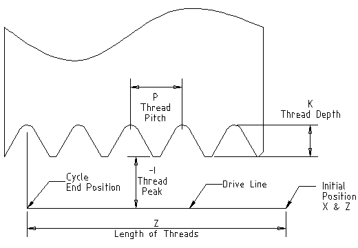
- Drive Line
-
A line through the initial X position parallel to the Z.
- P-
-
The "thread pitch" in distance per revolution.
- Z-
-
The final position of threads. At the end of the cycle the tool will be at this Z position.
- I-
-
The "thread peak" offset from the "drive line". Negative I values are external threads, and positive I values are internal threads. Generally the material has been turned to this size before the G76 cycle.
- J-
-
A positive value specifying the "initial cut depth". The first threading cut will be J beyond the "thread peak" position.
- K-
-
A positive value specifying the "full thread depth". The final threading cut will be K beyond the "thread peak" position.
Optional settings
- R-
-
The "depth degression". R1.0 selects constant depth on successive threading passes. R2.0 selects constant area. Values between 1.0 and 2.0 select decreasing depth but increasing area. Values above 2.0 select decreasing area. Beware that unnecessarily high degression values will cause a large number of passes to be used. (degression = a descent by stages or steps.)
- Q-
-
The "compound slide angle" is the angle (in degrees) describing to what extent successive passes should be offset along the drive line. This is used to cause one side of the tool to remove more material than the other. A positive Q value causes the leading edge of the tool to cut more heavily. Typical values are 29, 29.5 or 30.
- H-
-
The number of "spring passes". Spring passes are additional passes at full thread depth. If no additional passes are desired, program H0.
Tapered entry and exit moves can be programmed using E- and L-.
- E-
-
Specifies the distance along the drive line used for the taper. The angle of the taper will be so the last pass tapers to the thread crest over the distance specified with E.` E0.2` will give a taper for the first/last 0.2 length units along the thread. For a 45 degree taper program E the same as K
- L-
-
Specifies which ends of the thread get the taper. Program L0 for no taper (the default), L1 for entry taper, L2 for exit taper, or L3 for both entry and exit tapers. Entry tapers will pause at the drive line to synchronize with the index pulse then feed in to the beginning of the taper. No entry taper and the tool will rapid to the cut depth then synchronize and begin the cut.
The tool is moved to the initial X and Z positions prior to issuing the G76. The X position is the "drive line" and the Z position is the start of the threads.
The tool will pause briefly for synchronization before each threading pass, so a relief groove will be required at the entry unless the beginning of the thread is past the end of the material or an entry taper is used.
Unless using an exit taper, the exit move (traverse to original X) is not synchronized to the spindle speed. With a slow spindle, the exit move might take only a small fraction of a revolution. If the spindle speed is increased after several passes are complete, subsequent exit moves will require a larger portion of a revolution, resulting in a very heavy cut during the exit move. This can be avoided by providing a relief groove at the exit, or by not changing the spindle speed while threading.
The final position of the tool will be at the end of the "drive line". A safe Z move will be needed with an internal thread to remove the tool from the hole.
The sample program g76.ngc shows the use of the G76 canned cycle, and can be previewed and executed on any machine using the sim/lathe.ini configuration.
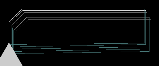
The following example shows the result of running this G-Code:
G0 Z-.5 X .2
G76 P0.05 Z-1 I-.075 J0.008 K0.045 Q29.5 L2 E0.045
The tool is in the final position after the G76 cycle is completed. You can see the entry path on the right from the Q29.5 and the exit path on the left from the L2 E0.045. The white lines are the cutting moves.
32. G80 Cancel Modal Motion
Program G80 to ensure no axis motion will occur. It is an error if:
-
Axis words are programmed when G80 is active, unless a modal group 0 Gcode is programmed which uses axis words.
33. Canned Cycles
The canned cycles G81 through G89 are described in this section. Two examples are given with the description of G81 below.
All canned cycles are performed with respect to the currently-selected plane. Any of the six planes may be selected. Throughout this section, most of the descriptions assume the XY-plane has been selected. The behavior is analogous if another plane is selected, and the correct words must be used. For instance, in the G17.1 plane, the action of the canned cycle is along W, and the locations or increments are given with U and V. In this case substitute U,V,W for X,Y,Z in the instructions below.
Rotary axis words are not allowed in canned cycles. When the active plane is one of the XYZ family, the UVW axis words are not allowed. Likewise, when the active plane is one of the UVW family, the XYZ axis words are not allowed.
33.1. Common Words
All canned cycles use X, Y, Z, or U, V, W groups depending on the plane selected and R words. The R (usually meaning retract) position is along the axis perpendicular to the currently selected plane (Z-axis for XY-plane, etc.) Some canned cycles use additional arguments.
33.2. Sticky Words
For canned cycles, we will call a number "sticky" if, when the same cycle is used on several lines of code in a row, the number must be used the first time, but is optional on the rest of the lines. Sticky numbers keep their value on the rest of the lines if they are not explicitly programmed to be different. The R number is always sticky.
In incremental distance mode X, Y, and R numbers are treated as increments from the current position and Z as an increment from the Z-axis position before the move involving Z takes place. In absolute distance mode, the X, Y, R, and Z numbers are absolute positions in the current coordinate system.
33.3. Repeat Cycle
The L number is optional and represents the number of repeats.
 L10 , you will
get 10 cycles. The first cycle will be distance X,Y from
the original location. The R and Z positions do not change during the
repeats. The L number is not sticky. In absolute distance mode,
L10 , you will
get 10 cycles. The first cycle will be distance X,Y from
the original location. The R and Z positions do not change during the
repeats. The L number is not sticky. In absolute distance mode,


33.4. Retract Mode
The height of the retract move at the end of each repeat (called "clear Z" in the descriptions below) is determined by the setting of the retract mode: either to the original Z position (if that is above the R position and the retract mode is G98, OLD_Z), or otherwise to the R position. See Section [sec:G98-G99-Set]
33.5. Canned Cycle Errors
It is an error if:
-
X, Y, and Z words are all missing during a canned cycle,
-
Axis words from different groups (XYZ) (UVW) are used together,
-
a P number is required and a negative P number is used,
-
an L number is used that does not evaluate to a positive integer,
-
rotary axis motion is used during a canned cycle,
-
inverse time feed rate is active during a canned cycle,
-
or cutter radius compensation is active during a canned cycle.
If the XY plane is active, the Z number is sticky, and it is an error if:
-
the Z number is missing and the same canned cycle was not already active,
-
or the R number is less than the Z number.
If other planes are active, the error conditions are analogous to the XY conditions above.
33.6. Preliminary and In-Between Motion
At the very beginning of the execution of any of the canned cycles, if the current Z position is below the R position, the Z-axis is traversed to the R position. This happens only once, regardless of the value of L.
In addition, at the beginning of the first cycle and each repeat, the following one or two moves are made
-
a straight traverse parallel to the XY-plane to the given XY-position,
-
a straight traverse of the Z-axis only to the R position, if it is not already at the R position.
If another plane is active, the preliminary and in-between motions are analogous.
34. G81 Drilling Cycle
G81 (X- Y- Z-) or (U- V- W-) R- L-
The G81 cycle is intended for drilling.
-
Preliminary motion, as described above.
-
Move the Z-axis only at the current feed rate to the Z position.
-
Retract the Z-axis at traverse rate to clear Z.
Example 1. Suppose the current position is (1, 2, 3) and the XY-plane has been selected, and the following line of NC code is interpreted.
G90 G81 G98 X4 Y5 Z1.5 R2.8
This calls for absolute distance mode (G90) and OLD_Z retract mode (G98) and calls for the G81 drilling cycle to be performed once. The X number and X position are 4. The Y number and Y position are 5. The Z number and Z position are 1.5. The R number and clear Z are 2.8. Old Z is 3. The following moves take place.
-
a traverse parallel to the XY-plane to (4,5,3)
-
a traverse parallel to the Z-axis to (4,5,2.8)
-
a feed parallel to the Z-axis to (4,5,1.5)
-
a traverse parallel to the Z-axis to (4,5,3)
Example 2. Suppose the current position is (1, 2, 3) and the XY-plane has been selected, and the following line of NC code is interpreted.
G91 G81 G98 X4 Y5 Z-0.6 R1.8 L3
This calls for incremental distance mode (G91) and OLD_Z retract mode (G98) and calls for the G81 drilling cycle to be repeated three times. The X number is 4, the Y number is 5, the Z number is -0.6 and the R number is 1.8. The initial X position is 5 (=1+4), the initial Y position is 7 (=2+5), the clear Z position is 4.8 (=1.8+3), and the Z position is 4.2 (=4.8-0.6). Old Z is 3.
The first move is a traverse along the Z-axis to (1,2,4.8), since old Z < clear Z.
The first repeat consists of 3 moves.
-
a traverse parallel to the XY-plane to (5,7,4.8)
-
a feed parallel to the Z-axis to (5,7, 4.2)
-
a traverse parallel to the Z-axis to (5,7,4.8)
The second repeat consists of 3 moves. The X position is reset to 9 (=5+4) and the Y position to 12 (=7+5).
-
a traverse parallel to the XY-plane to (9,12,4.8)
-
a feed parallel to the Z-axis to (9,12, 4.2)
-
a traverse parallel to the Z-axis to (9,12,4.8)
The third repeat consists of 3 moves. The X position is reset to 13 (=9+4) and the Y position to 17 (=12+5).
-
a traverse parallel to the XY-plane to (13,17,4.8)
-
a feed parallel to the Z-axis to (13,17, 4.2)
-
a traverse parallel to the Z-axis to (13,17,4.8)
35. G82 Drilling Cycle with Dwell
G82 (X- Y- Z-) or (U- V- W-) R- L- P-
The G82 cycle is intended for drilling with a dwell at the bottom of the hole.
-
Preliminary motion, as described above.
-
Move the Z-axis only at the current feed rate to the Z position.
-
Dwell for the P number of seconds.
-
Retract the Z-axis at traverse rate to clear Z.
36. G83 Peck Drilling
G83 (X- Y- Z-) or (U- V- W-) R- L- Q-
The G83 cycle (often called peck drilling) is intended for deep drilling or milling with chip breaking. The retracts in this cycle clear the hole of chips and cut off any long stringers (which are common when drilling in aluminum). This cycle takes a Q number which represents a "delta" increment along the Z-axis. The retract before final depth will always be to the "retract" plane even if G98 is in effect. The final retract will honor the G98/99 in effect.
-
Preliminary motion, as described above.
-
Move the Z-axis only at the current feed rate downward by delta or to the Z position, whichever is less deep.
-
Rapid back out to the retract plane specified by the R word.
-
Rapid back down to the current hole bottom, backed off a bit.
-
Repeat steps 2, 3, and 4 until the Z position is reached at step 2.
-
Retract the Z-axis at traverse rate to clear Z.
It is an error if:
-
the Q number is negative or zero.
37. G84 Right-Hand Tapping
This code is currently unimplemented in EMC2. It is accepted, but the behavior is undefined. See sections [sec:G33-Spindle-Sync] and [sec:G33.1-Rigid-Tapping]
38. G85 Boring, No Dwell, Feed Out
G85 (X- Y- Z-) or (U- V- W-) R- L-
The G85 cycle is intended for boring or reaming, but could be used for drilling or milling.
-
Preliminary motion, as described above.
-
Move the Z-axis only at the current feed rate to the Z position.
-
Retract the Z-axis at the current feed rate to clear Z.
39. G86 Boring, Spindle Stop, Rapid Out
G86 (X- Y- Z-) or (U- V- W-) R- L- P-
The G86 cycle is intended for boring. This cycle uses a P number for the number of seconds to dwell.
-
Preliminary motion, as described above.
-
Move the Z-axis only at the current feed rate to the Z position.
-
Dwell for the P number of seconds.
-
Stop the spindle turning.
-
Retract the Z-axis at traverse rate to clear Z.
-
Restart the spindle in the direction it was going.
The spindle must be turning before this cycle is used. It is an error if:
-
the spindle is not turning before this cycle is executed.
40. G87 Back Boring
This code is currently unimplemented in EMC2. It is accepted, but the behavior is undefined.
41. G88 Boring, Spindle Stop, Manual Out
This code is currently unimplemented in EMC2. It is accepted, but the behavior is undefined.
42. G89 Boring, Dwell, Feed Out
G89 (X- Y- Z-) or (U- V- W-) R- L- P-
The G89 cycle is intended for boring. This cycle uses a P number, where P specifies the number of seconds to dwell.
-
Preliminary motion, as described above.
-
Move the Z-axis only at the current feed rate to the Z position.
-
Dwell for the P number of seconds.
-
Retract the Z-axis at the current feed rate to clear Z.
43. G90, G91 Set Distance Mode
G90 is Absolute Distance Mode +
G91 is Incremental Distance Mode
Interpretation of G Code can be in one of two distance modes: absolute or incremental.
To go into absolute distance mode, program G90. In absolute distance mode, axis numbers (X, Y, Z, A, B, C, U, V, W) usually represent positions in terms of the currently active coordinate system. Any exceptions to that rule are described explicitly in section [sec:G81-G89].
To go into incremental distance mode, program G91. In incremental distance mode, axis numbers usually represent increments from the current coordinate.
44. G90.1, G91.1 Arc Distance Mode
G90.1 Absolute Distance Mode for I, J & K offsets.
-
I and J both must be specified or it is an error
G91.1 Incremental Distance Mode for I, J & K offsets.
-
Returns I, J & K to their normal behavior.
45. G92, G92.1, G92.2, G92.3 Coordinate System Offsets
G92 X- Y- Z- A- B- C- U- V- W-
See Section [cha:Coordinate-System] for an overview of coordinate systems.
See Section [sec:G92-Offsets] for more information on Offsets.
To make the current point have the coordinates you want (without motion), program G92 X- Y- Z- A- B- C- U- V- W- , where the axis words contain the axis numbers you want. All axis words are optional, except that at least one must be used. If an axis word is not used for a given axis, the coordinate on that axis of the current point is not changed. It is an error if:
-
all axis words are omitted.
When G92 is executed, the origins of all coordinate systems move. They move such that the value of the current controlled point, in the currently active coordinate system, becomes the specified value. All coordinate system’s origins are offset this same distance.
For example, suppose the current point is at X=4 and there is currently no G92 offset active. Then G92 x7 is programmed. This moves all origins -3 in X, which causes the current point to become X=7. This -3 is saved in parameter 5211.
Being in incremental distance mode has no effect on the action of G92.
G92 offsets may be already be in effect when the G92 is called. If this is the case, the offset is replaced with a new offset that makes the current point become the specified value.
To reset axis offsets to zero, program G92.1 or G92.2. G92.1 sets parameters 5211 to 5219 to zero, whereas G92.2 leaves their current values alone.
To set the axis offset to the values saved in parameters 5211 to 5219, program G92.3.
You can set axis offsets in one program and use the same offsets in another program. Program G92 in the first program. This will set parameters 5211 to 5219. Do not use G92.1 in the remainder of the first program. The parameter values will be saved when the first program exits and restored when the second one starts up. Use G92.3 near the beginning of the second program. That will restore the offsets saved in the first program.
EMC2 stores the G92 offsets and reuses them on the next run of a program. To prevent this, one can program a G92.1 (to erase them), or program a G92.2 (to remove them - they are still stored).
46. G93, G94, G95: Set Feed Rate Mode
G93 is Inverse Time Mode
G94 is Units per Minute Mode
G95 is Units per Revolution Mode.
Three feed rate modes are recognized: units per minute, inverse time, and units per revolution. Program G94 to start the units per minute mode. Program G93 to start the inverse time mode. Program G95 to start the units per revolution mode.
In units per minute feed rate mode, an F word is interpreted to mean the controlled point should move at a certain number of inches per minute, millimeters per minute, or degrees per minute, depending upon what length units are being used and which axis or axes are moving.
In units per revolution mode, an F word is interpreted to mean the controlled point should move a certain number of inches per revolution of the spindle, depending on what length units are being used and which axis or axes are moving. G95 is not suitable for threading, for threading use G33 or G76.
In inverse time feed rate mode, an F word means the move should be completed in [one divided by the F number] minutes. For example, if the F number is 2.0, the move should be completed in half a minute.
When the inverse time feed rate mode is active, an F word must appear on every line which has a G1, G2, or G3 motion, and an F word on a line that does not have G1, G2, or G3 is ignored. Being in inverse time feed rate mode does not affect G0 (rapid traverse) motions.
It is an error if:
-
inverse time feed rate mode is active and a line with G1, G2, or G3 (explicitly or implicitly) does not have an F word.
-
A new feed rate is not specified after switching to G94 or G95
47. G96, G97 Spindle Control Mode
G96 D[max spindle speed] S[units per minute] is Constant Surface Speed Mode +
G97 is RPM Mode
Two spindle control modes are recognized: revolutions per minute, and CSS (constant surface speed). Program G96 D- S- to select constant surface speed of S feet per minute (if G20 is in effect) or meters per minute (if G21 is in effect). The maximum spindle speed is set by the D- number in revolutions per minute.
When using G96, ensure that X0 in the current coordinate system (including offsets and tool lengths) is the center of rotation or EMC will not give the desired spindle speed. G96 is not affected by radius or diameter mode.
Program G97 to select RPM mode.
It is an error if:
-
S is not specified with G96
-
A feed move is specified in G96 mode while the spindle is not turning
48. G98, G99 Set Canned Cycle Return Level
G98 Retract to the position that axis was in just before this series
    of one or more contiguous canned cycles was started. +
G99 Retract to the position specified by the R word of the canned cycle.
When the spindle retracts during canned cycles, there are two options to indicate how it retracts: (1) Withdrawal perpendicular to the current position to the position indicated by the R word, or (2) Withdrawal perpendicular to the current position to the position which was that of this axis just before the start of the canned cycle (unless the position is less than that indicated by the R word, in which case the latter will would be used).
To use (1), program G99. To use (2), program G98. Remember that the R word has different meanings mode absolute displacement and incremental mode of travel.
The "initial" (G98) plane is reset any time cycle motion mode is abandoned, whether explicitly (G80) or implicitly (any motion code that is not a cycle). Switching among cycle modes (say G81 to G83) does NOT reset the "initial" plane. It is possible to switch between G98 and G99 during a series of cycles.
M Codes
1. M0, M1, M2, M30, M60 Program Stopping and Ending
To pause a running program temporarily (regardless of the setting of the optional stop switch), program M0. EMC2 remains in the Auto Mode so MDI and other manual actions are not enabled.
To pause a running program temporarily (but only if the optional stop switch is on), program M1. EMC2 remains in the Auto Mode so MDI and other manual actions are not enabled.
It is OK to program M0 and M1 in MDI mode, but the effect will probably not be noticeable, because normal behavior in MDI mode is to stop after each line of input anyway.
To exchange pallet shuttles and then stop a running program temporarily (regardless of the setting of the optional stop switch), program M60.
If a program is stopped by an M0, M1, or M60, pressing the cycle start button will restart the program at the following line.
To end a program, program M2. To exchange pallet shuttles and then end a program, program M30. Both of these commands have the following effects:
-
Change from Auto mode to MDI mode.
-
Origin offsets are set to the default (like G54).
-
Selected plane is set to XY plane (like G17).
-
Distance mode is set to absolute mode (like G90).
-
Feed rate mode is set to units per minute (like G94).
-
Feed and speed overrides are set to ON (like M48).
-
Cutter compensation is turned off (like G40).
-
The spindle is stopped (like M5).
-
The current motion mode is set to feed (like G1).
-
Coolant is turned off (like M9).
No more lines of code in an RS274/NGC file will be executed after the M2 or M30 command is executed. Pressing cycle start will start the program at the beginning of the file.
2. M3, M4, M5 Spindle Control
To start the spindle clockwise at the "S" speed, program M3.
To start the spindle counterclockwise at the "S" speed, program M4.
To stop the spindle from turning, program M5.
It is OK to use M3 or M4 if the spindle speed is set to zero. If this is done (or if the speed override switch is enabled and set to zero), the spindle will not start turning. If, later, the spindle speed is set above zero (or the override switch is turned up), the spindle will start turning. It is OK to use M3 or M4 when the spindle is already turning or to use M5 when the spindle is already stopped.
3. M6 Tool Change
3.1. Manual Tool Change
If the HAL component hal_manualtoolchange is loaded, M6 will stop the spindle and prompt the user to change the tool. For more information on hal_manualtoolchange see Section ([sec:Manual-Tool-Change])
3.2. Tool Changer
To change a tool in the spindle from the tool currently in the spindle to the tool most recently selected (using a T word - see Section [sub:T-Select-Tool]), program M6. When the tool change is complete:
-
The spindle will be stopped.
-
The tool that was selected (by a T word on the same line or on any line after the previous tool change) will be in the spindle. The T number is an integer giving the changer slot of the tool (not its id).
-
If the selected tool was not in the spindle before the tool change, the tool that was in the spindle (if there was one) will be in its changer slot.
-
If configured in the .ini file some axis positions may move when a M6 is issued. See the EMCIO section of the Integrator’s Manual for more information on tool change options.
-
No other changes will be made. For example, coolant will continue to flow during the tool change unless it has been turned off by an M9.
-
The tool length offset is not changed, use G43 to change the tool length offset.
The tool change may include axis motion. It is OK (but not useful) to program a change to the tool already in the spindle. It is OK if there is no tool in the selected slot; in that case, the spindle will be empty after the tool change. If slot zero was last selected, there will definitely be no tool in the spindle after a tool change.
4. M7, M8, M9 Coolant Control
To turn mist coolant on, program M7.
To turn flood coolant on, program M8.
To turn all coolant off, program M9.
It is always OK to use any of these commands, regardless of what coolant is on or off.
5. Overrides
5.1. M48, M49 Override Control
To enable the spindle speed and feed rate override controls, program M48. To disable both controls, program M49. See Section [sub:Feed-Interaction] for more details. It is OK to enable or disable the controls when they are already enabled or disabled. These controls can also be toggled individually using M50 and M51 as described in the sections [sub:M50-Feed-Override] and [sub:M51-Spindle-Override].
5.2. M50 Feed Override Control
To enable the feed rate override control, program M50 or M50 P1. To disable the control, program M50 P0. While disabled the feed override will have no influence, and the motion will be executed at programmed feed rate. (unless there is an adaptive feed rate override active).
5.3. M51 Spindle Speed Override Control
To enable the spindle speed override control, program M51 or M51 P1. To disable the control program M51 P0. While disabled the spindle speed override will have no influence, and the spindle speed will have the exact program specified value (using the S-word as described in [sub:S-Set-Spindle]).
5.4. M52 Adaptive Feed Control
To use an adaptive feed, program M52 or M52 P1. To stop using adaptive feed, program M52 P0. When adaptive feed is enabled, some external input value is used together with the user interface feed override value and the commanded feed rate to set the actual feed rate. In EMC2, the HAL pin motion.adaptive-feed is used for this purpose. Values on motion.adaptive-feed should range from 0 (feed hold) to 1 (full speed).
5.5. M53 Feed Stop Control
To enable the feed stop switch, program M53 or M53 P1. To disable the switch program M53 P0 . Enabling the feed stop switch will allow motion to be interrupted by means of the feed stop control. In EMC2, the HAL pin motion.feed-hold is used for this purpose. Values of 1 will cause the motion to stop (if M53 is active).
6. M61 Set Current Tool Number
To change the current tool number while in MDI or Manual mode program a M61 Qxx in the MDI window. One use is when you power up EMC with a tool currently in the spindle you can set that tool number without doing a tool change.
It is an error if:
-
Q- is not 0 or greater
7. M62 to M65 Output Control
To control a digital output bit, program M- P-, where the M-word ranges from 62 to 65, and the P-word ranges from 0 to a default value of 3. If needed the the number of I/O can be increased by using the num_dio parameter when loading the motion controller. See the Integrator’s Manual Configuration Section EMC and HAL section for more information.
-
The P- word specifies the digital output number.
M62:: Turn on digital output synchronized with motion
M63:: Turn off digital output synchronized with motion
M64:: Turn on digital output immediately
M65:: Turn off digital output immediately
The M62 & M63 commands will be queued. Subsequent commands referring to the same output number will overwrite the older settings. More than one output change can be specified by issuing more than one M62/M63 command.
The actual change of the specified outputs will happen at the beginning of the next motion command. If there is no subsequent motion command, the queued output changes won’t happen. It’s best to always program a motion g-code (G0, G1, etc) right after the M62/63.
M64 & M65 happen immediately as they are received by the motion controller. They are not synchronized with movement, and they will break blending.
8. M66 Input Control
To read the value of an analog or digital input pin, program M66 P- E- L- Q-, where the P-word and the E-word ranges from 0 to 3. If needed, the the number of I/O can be increased by using the num_dio or num_aio parameter when loading the motion controller. See the Integrator’s Manual, Configuration Section, EMC and HAL subsection, for more information. Only one of the P or E words must be present. It is an error if they are both missing.
M66:: Wait on an input
-
The P- word specifies the digital input number.
-
The E- word specifies the analog input number.
-
The L- word specifies the wait type:
- 0
-
WAIT_MODE_IMMEDIATE - no waiting, returns immediately. The current value of the input is stored in parameter #5399
- 1
-
WAIT_MODE_RISE - waits for the selected input to perform a rise event.
- 2
-
WAIT_MODE_FALL - waits for the selected input to perform a fall event.
- 3
-
WAIT_MODE_HIGH - waits for the selected input to go to the HIGH state.
- 4
-
WAIT_MODE_LOW - waits for the selected input to go to the LOW state.
-
The Q-word specifies the timeout in seconds for waiting. If the timeout is exceeded, the wait is interrupt, and the variable #5399 will be holding the value -1. The Q value is ignored if the L-word is zero (IMMEDIATE). A Q value of zero is an error if the L-word is non-zero.
-
Mode 0 is the only one permitted for an analog input.
M66 wait on an input stops further execution of the program, until the selected event (or the programmed timeout) occurs.
It is an error to program M66 with both a P-word and an E-word (thus selecting both an analog and a digital input).In EMC2 these inputs are not monitored in real time and thus should not be used for timing-critical applications.
9. M67 Analog Output
To control an analog output synchronized with motion, program M67 E- Q-, where the E word ranges from 0 to the default maximum of 3 and Q is the value to set. The number of I/O can be increased by using the num_aio parameter when loading the motion controller. See the "EMC2 and HAL" chapter in the Configuration Section of the Integrator Manual for more information on the Motion Controller. M67 functions the same as M62-63. See the M62-65 section for information about queuing output commands synchronized with motion.
10. M68 Analog Output
To control an analog output immediately, program `M68 E- Q-, ` where the E word ranges from 0 to the default maximum of 3 and Q is the value to set. The number of I/O can be increased by using the num_aio parameter when loading the motion controller. See the "EMC2 and HAL" chapter in the Configuration Section of the Integrator’s Manual for more information on the Motion Controller. M68 functions the same as M64-65. See the M62-65 section for information about immediate output commands.
11. M100 to M199 User Defined Commands
To invoke a user-defined command, program M1nn P- Q- where P- and Q- are both optional and must be a number. The external program "M1nn" must be in the directory named in [DISPLAY] PROGRAM_PREFIX in the ini file and is executed with the P and Q values as its two arguments. Execution of the RS274NGC file pauses until the invoked program exits. Any valid executable file can be used.
The error "Unknown M code used" denotes one of the following
-
The specified User Defined Command does not exist
-
The file is not an executable file
For example to open and close a collet closer that is controlled by a parport pin using a bash script file using M101 and M102. Create two files called M101 and M102. Set them as executable files (typically right click/properties/permissions) before running EMC2. Make sure the parport pin is not connected to anything in a HAL file.
M101 (file name)
#!/bin/sh
# file to turn on parport pin 14 to open the collet closer
halcmd setp parport.0.pin-14-out True
exit 0
M102 (file name)
#!/bin/sh
# file to turn off parport pin 14 to open the collet closer
halcmd setp parport.0.pin-14-out False
exit 0
To pass a variable to a M1nn file you use the P and Q option like this:
M100 P123.456 Q321.654
In your M100 file it might look like this:
#!/bin/sh
voltage=$1
feedrate=$2
halcmd setp thc.voltage $voltage
halcmd setp thc.feedrate $feedrate
exit 0
O Codes
O-codes provide for flow control in NC programs. Each block has an associated number, which is the number used after O. Care must be taken to properly match the O-numbers. O codes use the letter "O" not the number zero as the first character in the number like O100.
The behavior is undefined if:
-
Other words are used on a line with an O- word
-
Comments are used on a line with an O-word
1. Subroutines: sub, endsub, return, call
Subroutines extend from a O- sub to an O- endsub . The lines inside the subroutine (the "body") are not executed in order; instead, they are executed each time the subroutine is called with O- call.
O100 sub (subroutine to move to machine home)
G0 X0 Y0 Z0
O100 endsub
(many intervening lines)
O100 call
Inside a subroutine, O- return can be executed. This immediately returns to the calling code, just as though O- endsub was encountered.
O- call takes up to 30 optional arguments, which are passed to the subroutine as #1, #2 , …, #N. Parameters from #N+1 to #30 have the same value as in the calling context. On return from the subroutine, the values of parameters #1 through #30 (regardless of the number of arguments) will be restored to the values they had before the call. Parameters #1 - #30 are local to the subroutine.
Because "1 2 3 " is parsed as the number 123, the parameters must be enclosed in square brackets. The following calls a subroutine with 3 arguments:
O200 call [1] [2] [3]
Subroutine bodies may not be nested. They may only be called after they are defined. They may be called from other functions, and may call themselves recursively if it makes sense to do so. The maximum subroutine nesting level is 10.
Subroutines do not have "return values", but they may change the value of parameters above #30 and those changes will be visible to the calling code. Subroutines may also change the value of global named parameters.
2. Looping: do, while, endwhile, break, continue
The "while loop" has two structures: while/endwhile, and do/while. In each case, the loop is exited when the "while" condition evaluates to false.
(draw a sawtooth shape)
F100
#1 = 0
O101 while [#1 lt 10]
G1 X0
G1 Y[#1/10] X1
#1 = [#1+1]
O101 endwhile
Inside a while loop, O- break immediately exits the loop, and O- continue immediately skips to the next evaluation of the while condition. If it is still true, the loop begins again at the top. If it is false, it exits the loop.
3. Conditional: if, else, endif
The "if" conditional executes one group of statements if a condition is true and another if it is false.
(Set feed rate depending on a variable)
O102 if [#2 GT 5]
F100
O102 else
F200
O102 endif
4. Repeat
The "repeat" will execute the statements inside of the repeat/endrepeat the specified number of times. The example shows how you might mill a diagonal series of shapes starting at the present position.
(Mill 5 diagonal shapes)
G91 (Incremental mode)
O103 repeat [5]
... (insert milling code here)
G0 X1 Y1 (diagonal move to next position)
O103 endrepeat
G90 (Absolute mode)
5. Indirection
The O-number may be given by a parameter or calculation.
O[#101+2] call
6. Computing values in O-words
In O-words, Parameters (section [sub:Numbered-Parameters]), Expressions (section [sub:Expressions]), Binary Operators (section [sub:Binary-Operators]), and Functions (table [cap:Functions]) are particularly useful.
7. Calling Files
To call a separate file with a subroutine name the file the same as your call and include a sub and endsub in the file. The file must be in the directory pointed to by PROGRAM_PREFIX. The file name can include lowercase letters, numbers, dash, and underscore only.
    o<myfile> call (a named file)
or
    o123 call (a number file)
In the called file you must include the oxxx sub and endsub and the file must be a valid file.
myfile.ngc
o<myfile> sub
...
o<myfile> endsub
M2
Other Codes
1. F: Set Feed Rate
To set the feed rate, program F<n> where "n" is a number. The application of the feed rate is as described in Section [sub:Feed-Rate], unless inverse time feed rate mode is in effect, in which case the feed rate is as described in Section [sec:G93-G94-G95-Mode].
2. S: Set Spindle Speed
To set the speed in revolutions per minute (RPM) of the spindle, program S-. The spindle will turn at that speed when it has been programmed to start turning. It is OK to program an S word whether the spindle is turning or not. If the speed override switch is enabled and not set at 100%, the speed will be different from what is programmed. It is OK to program S0, the spindle will not turn if that is done.
It is an error if:
-
the S number is negative.
As described in Section [sec:G84-Right-Hand-Tapping], if a G84 (tapping) canned cycle is active and the feed and speed override switches are enabled, the one set at the lower setting will take effect. The speed and feed rates will still be synchronized. In this case, the speed may differ from what is programmed, even if the speed override switch is set at 100%.
3. T: Select Tool
To select a tool, program T<n>, where the <n> number is the carousel slot for the tool. The tool is not changed until an M6 is programmed (see Section [sec:M6-Tool-Change]). The T word may appear on the same line as the M6 or on a previous line. It is OK, but not normally useful, if T words appear on two or more lines with no tool change. The carousel may move a lot, but only the most recent T word will take effect at the next tool change. It is OK to program T0; no tool will be selected. This is useful if you want the spindle to be empty after a tool change.
It is an error if:
-
a negative T number is used,
-
or a T number larger than the number of slots in the carousel is used.
On some machines, the carousel will move when a T word is programmed, at the same time machining is occurring. On such machines, programming the T word several lines before a tool change will save time. A common programming practice for such machines is to put the T word for the next tool to be used on the line after a tool change. This maximizes the time available for the carousel to move.
Rapid moves after a T<n> will not show on the AXIS preview until after a feed move. This is for machines that travel long distances to change the tool like a lathe. This can be very confusing at first. To turn this feature off for the current tool change program a G1 without any move after the T<n>.
4. Comments
Printable characters and white space inside parentheses is a comment. A left parenthesis always starts a comment. The comment ends at the first right parenthesis found thereafter. Once a left parenthesis is placed on a line, a matching right parenthesis must appear before the end of the line. Comments may not be nested; it is an error if a left parenthesis is found after the start of a comment and before the end of the comment. Here is an example of a line containing a comment:
G80 M5 (stop motion)
Comments are only informative, they do not cause a machine to do anything.
5. Messages
A comment contains a message if MSG appears after the left parenthesis and before any other printing characters. Variants of MSG which include white space and lower case characters are allowed. The rest of the characters before the right parenthesis are considered to be a message. Messages should be displayed on the message display device. Comments not containing messages need not be displayed there.
6. Probe Logging
A comment can also be used to specify a file for the results of G38.x probing. See section [sec:G38.x-Straight-Probe].
Often, general logging is more useful than probe logging. Using general logging, the format of the output data can be controlled.
6.1. General Logging
6.1.1. (LOGOPEN,filename)
Opens the named log file. If the file already exists, it is truncated.
6.1.2. (LOGAPPEND,filename)
Opens the named log file. If the file already exists, the data is appended.
6.1.3. (LOGCLOSE)
If the log file is open, it is closed.
6.1.4. (LOG,…)
The message “…” is expanded as described below and then written to the log file if it is open.
6.2. Debugging Messages
Comments that look like: (debug, rest of comment) are the same as comments like (msg, rest of comment) with the addition of special handling for parameters.
Comments that look like: (print, rest of comment) are output to stderr with special handling for parameters.
6.3. Parameters in special comments
In the DEBUG, PRINT and LOG comments, the values of parameters in the message are expanded.
For example: to print a named global variable to stderr (the default console window) add a line to your gcode like…
(print,endmill dia = #<_endmill_dia>)
Inside the above types of comments, sequences like #123 are replaced by the value of the parameter 123. Sequences like #<named parameter> are replaced by the value of the named parameter. Remember that named parameters will have white space removed from them. So, #<named parameter> is the same as #<namedparameter>.