Integrators Manual V2.5
This manual is a work in progress. If you are able to help with writing, editing, or graphic preparation please contact any member of the writing team or join and send an email to emc-users@lists.sourceforge.net.
Copyright (c) 2000-9 LinuxCNC.org
Permission is granted to copy, distribute and/or modify this
document under the terms of the GNU Free Documentation License,
Version 1.1 or any later version published by the Free Software
Foundation; with no Invariant Sections, no Front-Cover Texts, and
one Back-Cover Text: This EMC Handbook is the product of several
authors writing for linuxCNC.org. As you find it to be of value in
your work, we invite you to contribute to its revision and
growth.A copy of the license is included in the section entitled
GNU Free Documentation License. If you do not find the license
you may order a copy from Free Software Foundation, Inc. 59 Temple
Place, Suite 330 Boston, MA 02111-1307
1. Важные определения
1.1. Системы с шаговыми двигателями
1.1.1. Base Period
BASE_PERIOD это "стук сердца" вашего компьютера с EMC. Каждый период программный генератор шагов решает, не пришло ли время для следующего импульса шага. Более короткий период позволит генерировать больше импульсов в секунду, в пределах разумного. Но если вы зайдете слишком далеко, ваш компьютер будет тратить слишком много времени генерируя импульсы шагов и все остальное будет буквально ползти или может даже заблокируется. Latency (латентность) и требования драйвера шагового двигателя влияют на кратчайший период который вы можете использовать.
Наихудшая возможная латентность может случаться только несколько раз в минуту, и вероятность плохой латентности во время когда мотор меняет направление очень мало. Поэтому вы можете получать очень редкие ошибки, которые будут портить деталь от случая к случаю, и которые будет невозможно отследить.
Простейший способ избежать этих проблем - выбрать BASE_PERIOD который будет суммой самого длинного времени из требований драйвера и худшего значения latency вашего компьютера. Это не всегда лучшее решение, например, если вы работаете с двигателем с требованием 20мкс (микросекунд) времени удержания и ваш latency тест говорит, что ваша максимальная латентность 11мкс, тогда если вы установите BASE_PERIOD равным 20+11=31мкс и не такими уж хорошими 16 129 шагами в секунду.
Проблема в требовании 20мкс времени удержания. Это плюс 11мкс латентности заставляет вас использовать медленный 31мкс период. Но программный генератор шагов EMC2 имеет несколько параметров которые позволяют вам увеличить переменное время от одного периода до нескольких. Например, если steplen (длинна шага) изменена с 1 на 2, тогда будет два периода между началом и концом импульса шага. Также если dirhold (удержание сигнала направления) изменится с 1 до 3, будет как минимум три периода между импульсом шага и изменением пина направления.
Если мы сможем использовать dirhold для удовлетворения требования 20мкс, тогда следующее самое длинное время будет 4.5мкс. Добавим 11мкс латентности и получим минимальный период 15.5 мкс. Когда вы попробуете 15.5 мкс вы обнаружите, что компьютер неповоротливый, поэтому остановитесь на 16мкс. Если мы оставим dirhold на 1 (по умолчанию), тогда минимальное время между шагом и сменой направления будет 16мкс минус 11мкс латентности = 5мкс, которые недостаточны. Нам нужно еще 15 мкс. Так как период = 16мкс нам нужен еще один период. Поэтому меняем dirhold с 1 на 2. Теперь минимальное время с конца импульса шага до изменения пина направления равно 5+16=21мкс, и мы не должны беспокоится о том, что двигатель шагнет не в ту сторону из-за латентности.
Более подробно о stepgen смотрите в разделе ( [sec:Stepgen]).
1.1.2. Время шага
Время шага (Step Timing) и время между шагами (Step Space) на некоторых драйверах разное. В этом случае Точка шага становится важной. Если двигатель шагает на падающей фронте тогда выходной пин должен быть инвертирован.
1.2. Серво двигатели
1.2.1. Настройка
Серво системы должны быть отрегулированы, т.к. не так хорошо работают из коробки, как могли бы системы на шаговых двигателях. Это потому, что серводвигатели не "шагают" с определенным приращением как шаговые двигатели. PID это "Черная Магия" которая заставляет серводвигатель двигаться туда, куда вам хочется чтобы она двигалась и когда вам хочется чтобы она двигалась.
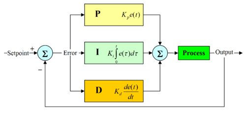
PID расшифровывается как Proportional, Integral, and Derivative (Пропорциональная, Интегральная и Производная). Пропорциональное значение определяет реакцию на текущее отклонение, Интегральное значение задает реакцию на основываясь на сумме недавних отклонений, а Производное значение определяет реакцию основываясь на скорости изменения отклонения. Они являются тремя общими математическими техниками которые применяются к решению задач сделать так чтобы работающий процесс следовал заданной точке. В случае EMC2 процесс который мы хотим контролировать это фактическое положение оси а заданная точка это положение оси заданное командой.
"Настраивая" эти три константы в алгоритме PID контроллера, контроллер сможет производить контрольные действия спроектированные для специфичных требований процесса. Ответ от контроллера может быть описан в терминах отзывчивости контроллера на ошибку, степени промаха контроллера мимо назначенной точки и степени колебания системы.
1.2.2. Пропорциональный член
Пропорцианальный (иногда называется gain(усиление/прирост)) делает изменения выхода, которые пропорциональны текущему значению отклонения. Высокое пропорциональное усиление приводит к существенному изменению на выходе для данного изменения изменения отклонения. Если пропорциональное усиление слишком велико, система может стать нестабильной. И наоборот, маленькое усиление приводит к маленькому ответу на большое входное отклонение. Если пропорциональное усиление слишком мало, то контролирующее действие может быть слишком маленьким для реакции на возмущения системы.
В отсутствие возмущений, чистое пропорциональное управление никогда не остановится на его целевом значении, он будет сохранять устойчивое состояние отклонения которое будет функцией зависящей от пропорционального усиления и усиления процесса. Несмотря на постоянное состояние отклонения, теория настройки и производственная практика указывают на то, что пропорциональный метод должен делать основной вклад в изменение вывода.
1.2.3. Интегральный член
Вклад интегрального метода (иногда называемого reset (восстановление)) пропорционален обоим величине отклонения и его продолжительности. Суммируя мгновенное отклонение за время (интегрируя отклонение) дает накопленный отступ который должен был быть исправлен ранее. Накопленное смещение умножается на коэффициент усиления и добавляется на выход контроллера.
Интегральный член (будучи добавленным к пропорциональному) ускоряет движение процесса в сторону заданной точки и устраняет остаточные стационарные погрешности которые возникают при только пропорциональном управлении. Однако, так как интегральный метод отвечает на накопленную ошибку из прошлого, он может вызывать промахи текущего значения мимо заданной точки (прохождение мимо заданной точки и последующее создание отклонения в обратную сторону).
1.2.4. Дифференциальный член
Скорость изменения отклонения процесса вычисляется определением приращения отклонения по времени (т.е. это первая производная отклонения по времени) и умножением этой скорости изменения на коэффициент усиления производной.
Производный член замедляет скорость изменения выхода контроллера и этот эффект наиболее заметен близко к заданной точке. Следовательно, управление по производной используется для того, чтобы уменьшить величину промаха который создает интегральный компонент и улучшает стабильность комбинации контроллер-процесс.
1.2.5. Настройка цикла
Если параметры PID контроллера (усиления пропорционального, интегрального и производного членов) выбраны некорректно, вход контролируемого процесса может быть не стабильным, т.е. его выход будет расходиться, с или без колебаний, и будет ограничен только поглощением или механической поломкой. Настройка цикла контроллера является подгонкой параметров до оптимальных значений для желаемой реакции контроллера.
1.2.6. Ручная настройка
Простой метод настройки: сначала устанавливаем значения I и D (интегральный и дифференциальный члены) равные 0. Увеличиваем P до тех пор пока цикл не начнет колебаться, затем P должен быть установлен равным приблизительно половине значения для отклика с "четверть амплитудным распадом". Затем увеличивайте I до тех пор, пока любое смещение не корректируется за адекватное время для процесса. Однако, слишком большое I будет вызывать нестабильность. В конце увеличиваем D, если это необходимо, до тех пор пока цикл не будет приемлемо быстро достигать своего эталона после больших возмущений. Однако, слишком большой D будет вызывать чрезмерную реакцию и промахи. Быстрый PID цикл обычно слегка проскакивает заданную точку, чтобы достичь ее быстрее; однако, некоторые системы не допускают промахов, в этих случаях требуется "переторможенный" цикл, для которого необходима установка заметно более низкого P, меньше чем половина значения, которое вызывает колебания.
1.3. RTAI
Real Time Application Interface (RTAI, интерфейс для приложений рельного времени) используется для предоставления лучшей производительности в реальном времени.
Измененное RTAI ядро позволяет вам писать приложения с точными временными рамками. RTAI дает возможность иметь вещи такие как программная генерация шагов, которые требуют точного тайминга.
1.3.1. ACPI
Advanced Configuration and Power Interface (ACPI, усовершенствованный интерфейс конфигурации и управления питанием) имеет много разных функций, большинство из которых влияют на RT производительность (например, управление питанием, понижение питания процессора, изменение частоты процессора, и т.д.). В ядре EMC2 (и возможно во всех модифицированных RTAI ядрах) поддержка ACPI выключена. ACPI также заботится о выключении питания системы после ее выключения (shutdown), вот почему вам нужно нажимать клавишу питания для полного выключения компьютера.
Configuration
1. Hardware
1.1. Latency Test
Latency is how long it takes the PC to stop what it is doing and respond to an external request. For EMC2 the request is BASE_THREAD that makes the periodic "heartbeat" that serves as a timing reference for the step pulses. The lower the latency, the faster you can run the heartbeat, and the faster and smoother the step pulses will be.
Latency is far more important than CPU speed. A lowly Pentium II that responds to interrupts within 10 microseconds each and every time can give better results than the latest and fastest P4 Hyperthreading beast.
The CPU isn’t the only factor in determining latency. Motherboards, video cards, USB ports, and a number of other things can hurt the latency. The best way to find out what you are dealing with is to run the RTAI latency test.
Generating step pulses in software has one very big advantage - it’s free. Just about every PC has a parallel port that is capable of outputting step pulses that are generated by the software. However, software step pulses also have some disadvantages:
-
limited maximum step rate
-
jitter in the generated pulses
-
loads the CPU
The best way to find out what you are dealing with is to run the HAL latency test. To run the test, open a terminal window from Applications/Accessories/Terminal (Ubuntu) and run the following command:
latency-test
You should see something like this:
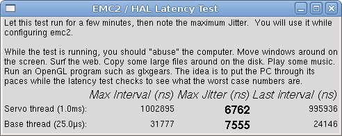
While the test is running, you should "abuse" the computer. Move windows around on the screen. Surf the web. Copy some large files around on the disk. Play some music. Run an OpenGL program such as glxgears. The idea is to put the PC through its paces while the latency test checks to see what the worst case numbers are.
|
Note
|
Do not run EMC2 or Stepconf while the latency test is running. |
The important numbers are the "max jitter". In the example above, that is 7555 nanoseconds, or 7.5 microseconds. Record this number, and enter it in Stepconf when it is requested.
In the example above, latency-test only ran for a few seconds. You should run the test for at least several minutes; sometimes the worst case latency doesn’t happen very often, or only happens when you do some particular action. For instance, one Intel motherboard worked pretty well most of the time, but every 64 seconds it had a very bad 300uS latency. Fortunately that was fixable see http://wiki.linuxcnc.org/cgi-bin/emcinfo.pl?FixingSMIIssues
So, what do the results mean? If your Max Jitter number is less than about 15-20 microseconds (15000-20000 nanoseconds), the computer should give very nice results with software stepping. If the max latency is more like 30-50 microseconds, you can still get good results, but your maximum step rate might be a little disappointing, especially if you use microstepping or have very fine pitch leadscrews. If the numbers are 100uS or more (100,000 nanoseconds), then the PC is not a good candidate for software stepping. Numbers over 1 millisecond (1,000,000 nanoseconds) mean the PC is not a good candidate for EMC, regardless of whether you use software stepping or not.
Note that if you get high numbers, there may be ways to improve them. Another PC had very bad latency (several milliseconds) when using the onboard video. But a $5 used video card solved the problem - EMC does not require bleeding edge hardware.
For more information on stepper tuning see the Stepper Tuning chapter ([cha:Stepper-Tuning]).
1.2. Port Address
For those who build their own hardware, one safeguard against shorting out an on-board parallel port - or even the whole motherboard - is to use an add-on parallel port card. Even if you don’t need the extra layer of safety, a parport card is a good way to add extra I/O lines with EMC.
One good PCI parport card is made with the Netmos 9815 chipset. It has good +5V signals, and can come in a single or dual ports.
To find the I/O addresses for these cards open a terminal window and use the list pci command:
lspci -v
Look for the entry with "NetMos" in it. Example of a 2-port card:
0000:01:0a.0 Communication controller: Netmos Technology PCI 9815 Multi-I/O Controller (rev 01)
      Subsystem: LSI Losgic / Symbios Logic 2POS (2 port parallel adapter)
      Flags: medium devsel, IRQ 5
      I/O ports at b800 [size=8]
      I/O ports at bc00 [size=8]
      I/O ports at c000 [size=8]
      I/O ports at c400 [size=8]
      I/O ports at c800 [size=8]
      I/O ports at cc00 [size=16]
From experimentation, I’ve found the first port (the on-card port) uses the third address listed (c000), and the second port (the one that attaches with a ribbon cable) uses the first address listed (b800).
You can then open an editor and put the addresses into the appropriate place in your .hal file.
loadrt hal_parport cfg="0x378 0xc000"
You must also direct EMC to run the "read" and "write" functions for the second card. For example,
addf parport.1.read base-thread 1
addf parport.1.write base-thread -1
Please note that your values will differ. The Netmos cards are Plug-N-Play, and might change their settings depending on which slot you put them into, so if you like to 'get under the hood' and re-arrange things, be sure to check these values before you start EMC.
2. Config Files
2.1. Files Used for Configuration
The EMC is configured with human readable text files. All of these
files can be read and edited in any of the common text file editors
available with most any Linux distribution.
[Don’t confuse a
text editor with a word processor. A text editor like
gedit or kwrite produce files that are plain text. They also produce
lines of text that are separated from each other. A word processor like
Open Office produce files with paragraphs and word wrapping and lots of
embedded codes that control font size and such. A text editor does none
of this.
]
You’ll need to be a bit careful when you edit these files. Some
mistakes will cause the start up to fail. These files are read whenever
the software starts up. Some of them are read repeatedly while the CNC
is running.
Configuration files include
- INI
-
The ini file overrides defaults that are compiled into the EMC code. It also provides sections that are read directly by the Hardware Abstraction Layer.
- HAL
-
The HAL files start up process modules and provide linkages between EMC signals and specific hardware pins.
- VAR
-
The var file is a way for the interpreter to save some values from one run to the next. These values are saved from one run to another but not always saved immediately. See the Parameters section of the G Code Manual for information on what each parameter is.
- TBL
-
The tbl file saves tool information. See the User Manual Tool File section for more info.
- NML
-
The nml file configures the communication channels used by the EMC. It is normally setup to run all of the communication within a single computer but can be modified to communicate between several computers.
 (((.emcrc))) This file saves user specific information and is created
to save the name of the directory when the user first selects an EMC
configuration.footnote:[Usually this file is in the users home
directory (e.g. /home/user/ )
]
Items marked (hal) are used only by the sample HAL files and are suggested as a good convention. Other items are used by EMC directly, and must always have the section and item names given.
3. INI File
3.1. The INI File Layout
A typical INI file follows a rather simple layout that includes;
-
comments.
-
sections,
-
variables.
Each of these elements is separated on single lines. Each end of line or newline character creates a new element.
3.1.1. Comments
A comment line is started with a ; or a # mark. When the ini reader sees either of these marks at the start a line, the rest of the line is ignored by the software. Comments can be used to describe what some INI element will do.
; This is my little mill configuration file.
; I set it up on January 12, 2006
Comments can also be used to select between several values of a single variable.
DISPLAY = axis
# DISPLAY = touchy
In this list, the DISPLAY variable will be set to axis because the other one is commented out. If someone carelessly edits a list like this and leaves two of the lines uncommented, the first one encountered will be used.
Note that inside a variable, the "#" and ";" characters do not denote comments:
INCORRECT = value     # and a comment
# Correct Comment
CORRECT = value
3.1.2. Sections
Related parts of an ini file are separated into sections. A section line looks like [THIS_SECTION]. The name of the section is enclosed in brackets. The order of sections is unimportant. The following sections are used by EMC:
-
[EMC] general information ( [sub:[EMC]-section])
-
[DISPLAY] settings related to the graphical user interface ( [sub:[DISPLAY]-section])
-
[FILTER] settings input filter programs ([sub:[FILTER]-Section])
-
[RS274NGC] settings used by the g-code interpreter ( [sub:[RS274NGC]-section])
-
[EMCMOT] settings used by the real time motion controller ( [sub:[EMCMOT]-section])
-
[HAL] specifies .hal files ( [sub:[HAL]-section])
-
[TASK] settings used by the task controller ( [sub:[TASK]-section])
-
[TRAJ] additional settings used by the real time motion controller ( [sub:[TRAJ]-section])
-
[AXIS_0] … [AXIS_n] individual axis variables ( [sub:[AXIS]-section])
-
[EMCIO] settings used by the I/O Controller ( [sub:[EMCIO]-Section])
-
[HALUI] MDI commands used by HALUI. See the HALUI chapter for more information ( [sub:MDI])
3.1.3. Variables
A variable line is made up of a variable name, an equals sign(=), and a value. Everything from the first non-white space character after the = up to the end of the line is passed as the value, so you can embed spaces in string symbols if you want to or need to. A variable name is often called a keyword.
The following sections detail each section of the configuration file, using sample values for the configuration lines.
Some of the variables are used by EMC, and must always use the section names and variable names shown. Other variables are used only by HAL, and the section names and variable names shown are those used in the sample configuration files.
3.1.4. Definitions
- Machine Unit
-
The unit of measurement for an axis is determined by the settings in the [TRAJ] section. A machine unit is equal to one unit as specified by LINEAR_UNITS or ANGULAR_UNITS.
3.2. Sections
3.2.1. [EMC] Section
- VERSION
-
=* *$Revision:* *1.3* *$ The version number for the INI file. The value shown here looks odd because it is automatically updated when using the Revision Control System. It’s a good idea to change this number each time you revise your file. If you want to edit this manually just change the number and leave the other tags alone.
- MACHINE
-
=* *My* *Controller This is the name of the controller, which is printed out at the top of most graphical interfaces. You can put whatever you want here as long as you make it a single line long.
- DEBUG = 0
-
Debug level 0 means no messages will be printed when EMC is run from a terminal. Debug flags are usually only useful to developers. See src/emc/nml_int/emcglb.h for other settings.
3.2.2. [DISPLAY] Section
Different user interface programs use different options, and not every option is supported by every user interface. The main two interfaces for EMC are AXIS and Touchy. Axis is an interface for use with normal computer and monitor, Touchy is for use with touch screens. Descriptions of the interfaces are in the Interfaces section of the User Manual.
DISPLAY = axis The name of the user interface to use. Valid options may include:
-
axis
-
touchy
-
keystick
-
mini
-
tkemc
-
xemc
- POSITION_OFFSET = RELATIVE
-
The coordinate system (RELATIVE or MACHINE) to show when the user interface starts. The RELATIVE coordinate system reflects the G92 and G5x coordinate offsets currently in effect.
- POSITION_FEEDBACK = ACTUAL
-
The coordinate value (COMMANDED or ACTUAL) to show when the user interface starts. The COMMANDED position is the ideal position requested by EMC. The ACTUAL position is the feedback position of the motors.
- MAX_FEED_OVERRIDE = 1.2
-
The maximum feed override the user may select. 1.2 means 120% of the programmed feed rate
- MIN_SPINDLE_OVERRIDE = 0.5
-
The minimum spindle override the user may select. 0.5 means 50% of the programmed spindle speed. (This is useful as it’s dangerous to run a program with a too low spindle speed).
- MAX_SPINDLE_OVERRIDE = 1.0
-
The maximum spindle override the user may select. 1.0 means 100% of the programmed spindle speed
- PROGRAM_PREFIX = ~/emc2/nc_files
-
The default location for g-code files and the location for user-defined M-codes
- INTRO_GRAPHIC = emc2.gif
-
The image shown on the splash screen
- INTRO_TIME = 5
-
The maximum time to show the splash screen
- CYCLE_TIME = 0.0500
-
Cycle time in seconds that display will sleep between polls.
The following [DISPLAY] items are used only if you select AXIS as your user interface program.
- DEFAULT_LINEAR_VELOCITY = .25
-
The default velocity for linear jogs, in machine units per second.
- MIN_VELOCITY = .01
-
The approximate lowest value the jog slider.
- MAX_LINEAR_VELOCITY = 1.0
-
The maximum velocity for linear jogs, in machine units per second.
- MIN_LINEAR_VELOCITY = .01
-
The approximate lowest value the jog slider.
- DEFAULT_ANGULAR_VELOCITY = .25
-
The default velocity for angular jogs, in machine units per second.
- MIN_ANGULAR_VELOCITY = .01
-
The approximate lowest value the jog slider.
- MAX_ANGULAR_VELOCITY = 1.0
-
The maximum velocity for angular jogs, in machine units per second.
- INCREMENTS = 1 mm, .5 in, …
-
Defines the increments available for incremental jogs. The INCREMENTS can be used to override the default. The values can be decimal numbers (e.g., 0.1000) or fractional numbers (e.g., 1/16), optionally followed by a unit (cm, mm, um, inch, in or mil). If a unit is not specified the machine unit is assumed. Metric and imperial distances may be mixed: INCREMENTS = 1 inch, 1 mil, 1 cm, 1 mm, 1 um is a valid entry.
- OPEN_FILE = /full/path/to/file.ngc
-
The file to show in the preview plot when AXIS starts. Use a blank string "" and no file will be loaded at start up.
- EDITOR = gedit
-
The editor to use when selecting File > Edit or File Edit Tool Table from the AXIS menu. This must be configured for these menu items to work. Another valid entry is gnome-terminal -e vim.
- PYVCP = /filename.xml
-
The pyVCP panel description file. See the pyVCP section for more information.
- LATHE = 1
-
This displays in lathe mode with a top view and with Radius and Diameter on the DRO.
- GEOMETRY = XYZABCUVW
-
Controls the preview and backplot of rotary motion. This item consists of a sequence of axis letters, optionally preceded by a "-" sign. Only axes defined in [TRAJ]AXES should be used. This sequence specifies the order in which the effect of each axis is applied, with a "-" inverting the sense of the rotation.
The proper GEOMETRY string depends on the machine configuration and the kinematics used to control it. The example string GEOMETRY=XYZBCUVW is for a 5-axis machine where kinematics causes UVW to move in the coordinate system of the tool and XYZ to move in the coordinate system of the material. The order of the letters is important, because it expresses the order in which the different transformations are applied. For example rotating around C then B is different than rotating around B then C. Geometry has no effect without a rotary axis. - ARCDIVISION = 64
-
Set the quality of preview of arcs. Arcs are previewed by dividing them into a number of straight lines; a semicircle is divided into ARCDIVISION parts. Larger values give a more accurate preview, but take longer to load and result in a more sluggish display. Smaller values give a less accurate preview, but take less time to load and may result in a faster display. The default value of 64 means a circle of up to 3 inches will be displayed to within 1 mil (.03%).
[In emc2.4 and earlier, the default value was 128. ]
- MDI_HISTORY_FILE =
-
The name of a local MDI history file. If this is not specified Axis will save the MDI history in /home/~/.axis_mdi_history in the home directory. This is useful if you have multiple configurations on one computer.
The following [DISPLAY] items are not used if you select AXIS as your user interface program.
- HELP_FILE = tkemc.txt
-
Path to help file (not used in AXIS).
3.2.3. [FILTER] Section
AXIS has the ability to send loaded files through a filter program. This filter can do any desired task: Something as simple as making sure the file ends with M2, or something as complicated as detecting whether the input is a depth image, and generating g-code to mill the shape it defines. The [FILTER] section of the ini file controls how filters work. First, for each type of file, write a PROGRAM_EXTENSION line. Then, specify the program to execute for each type of file. This program is given the name of the input file as its first argument, and must write rs274ngc code to standard output. This output is what will be displayed in the text area, previewed in the display area, and executed by EMC when Run.
- PROGRAM_EXTENSION = .extension Description
-
If your post processor outputs files in all caps you might want to add the following line:
PROGRAM_EXTENSION = .NGC XYZ Post Processor
The following lines add support for the image-to-gcode converter included with EMC2:
PROGRAM_EXTENSION = .png,.gif Greyscale Depth Image
It is also possible to specify an interpreter:
PROGRAM_EXTENSION = .py Python Script
In this way, any Python script can be opened, and its output is treated as g-code. One such example script is available at nc_files/holecircle.py. This script creates g-code for drilling a series of holes along the circumference of a circle. Many more g-code generators are on the EMC Wiki site http://wiki.linuxcnc.org/cgi-bin/emcinfo.pl.
If the environment variable AXIS_PROGRESS_BAR is set, then lines written to stderr of the form
FILTER_PROGRESS=%d
Sets the AXIS progress bar to the given percentage. This feature should be used by any filter that runs for a long time.
3.2.4. [RS274NGC] Section
- PARAMETER_FILE
-
The file located in the same directory as the ini file which contains the parameters used by the interpreter (saved between runs).
Example:
PARAMETER_FILE = myfile.var
- RS274NGC_STARTUP_CODE
-
A string of NC codes that the interpreter is initialized with. This is not a substitute for specifying modal g-codes at the top of each ngc file, because the modal codes of machines differ, and may be changed by g-code interpreted earlier in the session.
Example:
- SUBROUTINE_PATH
-
Specifies a colon (:) separated list of up to 10 directories to be searched when single-file subroutines are specified in gcode. These directories are searched after searching [DISPLAY]PROGRAM_PREFIX (if it is specified) and before searching [WIZARD]WIZARD_ROOT (if specified). The first matching subroutine file found in the search is used. Directories are specified relative to the current directory for the inifile or as absolute paths. The list must contain no intervening whitespace.
Example:
SUBROUTINE_PATH = ncsubroutines:/tmp/testsubs:lathesubs:millsubs
- USER_M_PATH
-
specifies a list of colon (:) separated directories (no intervening whitespace) for user defined functions. The maximum number of directories is defined at compile time by: USER_DEFINED_FUNCTION_MAX_DIRS=5. Directories are specified relative to the current directory for the inifile or as absolute paths. The list must contain no intervening whitespace.
Example:
USER_M_PATH = myfuncs:/tmp/mcodes:experimentalmcodes
A search is made for each possible user defined function, typically (M100-M199). The search order is:
-
[DISPLAY]PROGRAM_PREFIX (if specified)
-
If [DISPLAY]PROGRAM_PREFIX is not specified, search the default location: nc_files
-
Then search each directory in the list [RS274NGC]USER_M_PATH
The first executable M1xx found in the search is used for each M1xx.
3.2.5. [EMCMOT] Section
You may find other entries in this section and they should not be changed.
- BASE_PERIOD
-
= 50000 (hal) "Base" task period, in nanoseconds - this is the fastest thread in the machine.
On servo-based systems, there is generally no reason for BASE_PERIOD to be smaller than SERVO_PERIOD.
On machines with software step generation, the BASE_PERIOD determines the maximum number of steps per second. In the absence of long step length and step space requirements, the absolute maximum step rate is one step per BASE_PERIOD. Thus, the BASE_PERIOD shown above gives an absolute maximum step rate of 20000 steps per second. 50000ns is a fairly conservative value. The smallest usable value is related to the Latency Test result, the necessary step length, and the processor speed.
Choosing a BASE_PERIOD that is too low can lead to the "Unexpected real time delay" message, lockups, or spontaneous reboots. - SERVO_PERIOD
-
= 1000000 (hal) "Servo" task period is also in nanoseconds. This value will be rounded to an integer multiple of BASE_PERIOD. This value is used even on systems based on stepper motors.
This is the rate at which new motor positions are computed, following error is checked, PID output values are updated, and so on.
Most systems will not need to change this value. It is the update rate of the low level motion planner. - TRAJ_PERIOD
-
= 1000000 *(hal) Trajectory Planner task period in nanoseconds This value will be rounded to an integer multiple of *SERVO_PERIOD.
Except for machines with unusual kinematics (e.g., hexapods) there is no reason to make this value larger than SERVO_PERIOD.
3.2.6. [TASK] Section
- TASK = milltask
-
Specifies the name of the "task" executable. "task" does various things, such as communicate with the UIs over NML, communicate with the realtime motion planner over non-HAL shared memory, and interpret gcode. Currently there is only one task executable that makes sense for 99.9% of users, milltask In the dim mists of time (before HAL), it was frequently the case that an integrator would have to build a modified version of things like task, io, and motion for a specific machine.
- CYCLE_TIME
-
=* *0.0 01 The period, in seconds, at which EMCTASK will run. This parameter affects the polling interval when waiting for motion to complete, when executing a pause instruction, and when accepting a command from a user interface. There is usually no need to change this number.
3.2.7. [HAL] section
- HALFILE = example.hal
-
Execute the file example.hal at start up. If HALFILE is specified multiple times, the files are executed in the order they appear in the ini file. Almost all configurations will have at least one HALFILE , and stepper systems typically have two such files, one which specifies the generic stepper configuration (core_stepper.hal) and one which specifies the machine pin out (xxx_pinout.hal)
- HALCMD = command
-
Execute command as a single hal command. If HALCMD is specified multiple times, the commands are executed in the order they appear in the ini file. HALCMD lines are executed after all HALFILE lines.
- SHUTDOWN = shutdown.hal
-
Execute the file shutdown.hal when EMC is exiting. Depending on the hardware drivers used, this may make it possible to set outputs to defined values when EMC is exited normally. However, because there is no guarantee this file will be executed (for instance, in the case of a computer crash) it is not a replacement for a proper physical e-stop chain or other protections against software failure.
- POSTGUI_HALFILE = example2.hal
-
(Only with the AXIS GUI) Execute example2.hal after the GUI has created its HAL pins. See section [sec:pyvcp-with-axis] for more information.
3.2.8. [TRAJ] Section
The [TRAJ] section contains general parameters for the trajectory planning module in EMCMOT.
- COORDINATES
-
=* *X* Y* Z The names of the axes being controlled. X, Y, Z, A, B, C, U, V, and W are all valid. Only axis named in COORDINATES are accepted in g-code. This has no effect on the mapping from G-code axis names (X- Y- Z-) to joint numbers—for "trivial kinematics", X is always joint 0, A is always joint 4, and U is always joint 7, and so on. It is permitted to write an axis name twice (e.g., X Y Y Z for a gantry machine) but this has no effect.
- AXES = 3
-
One more than the number of the highest joint number in the system. For an XYZ machine, the joints are numbered 0, 1 and 2; in this case AXES should be 3. For an XYUV machine using "trivial kinematics", the V joint is numbered 7 and therefore AXES should be 8. For a machine with nontrivial kinematics (e.g., scarakins) this will generally be the number of controlled joints.
- HOME
-
=* *0* *0* *0 Coordinates of the homed position of each axis. Again for a fourth axis you will need 0 0 0 0. This value is only used for machines with nontrivial kinematics. On machines with trivial kinematics this value is ignored.
- LINEAR_UNITS = <units>
-
Specifies the machine units for linear axes. Possible choices are (in, inch, imperial, metric, mm).
This does not affect the linear units in NC code (the G20 and G21 words do this). - ANGULAR_UNITS = <units>
-
Specifies the machine units for rotational axes. Possible choices are deg, degree (360 per circle), rad, radian (2pi per circle), grad, or gon (400 per circle).
This does not affect the angular units of NC code. In RS274NGC, A-, B- and C- words are always expressed in degrees. - DEFAULT_VELOCITY
-
= 0.0167 The initial rate for jogs of linear axes, in machine units per second. The value shown equals one unit per minute.
- DEFAULT_ACCELERATION
-
= 2.0 In machines with nontrivial kinematics, the acceleration used for "teleop" (Cartesian space) jogs, in machine units per second per second.
- MAX_VELOCITY = 5.0
-
The maximum velocity for any axis or coordinated move, in machine units per second. The value shown equals 300 units per minute.
- MAX_ACCELERATION = 20.0
-
The maximum acceleration for any axis or coordinated axis move, in machine units per second per second.
- POSITION_FILE = position.txt
-
If set to a non-empty value, the joint positions are stored between runs in this file. This allows the machine to start with the same coordinates it had on shutdown. This assumes there was no movement of the machine while powered off. If unset, joint positions are not stored and will begin at 0 each time EMC is started. This can help on smaller machines without home switches.
- NO_FORCE_HOMING = 1
-
The default behavior is for EMC to force the user to home the machine before any MDI command or a program is run. Normally jogging only is allowed before homing. Setting NO_FORCE_HOMING = 1 allows the user to make MDI moves and run programs without homing the machine first. Interfaces without homing ability will need to have this option set to
-
*
Warning* : Using this will allow the machine to run past soft limits while in operation and is not generally desirable to allow this.
-
3.2.9. [AXIS_<num>] Section
The [AXIS_0], [AXIS_1], etc. sections contains general parameters for the individual components in the axis control module. The axis section names begin numbering at 0, and run through the number of axes specified in the [TRAJ] AXES entry minus 1.
-
AXIS_0 = X
-
AXIS_1 = Y
-
AXIS_2 = Z
-
AXIS_3 = A
-
AXIS_4 = B
-
AXIS_5 = C
-
AXIS_6 = U
-
AXIS_7 = V
-
AXIS_8 = W
- TYPE = LINEAR
-
The type of axes, either LINEAR or ANGULAR.
- WRAPPED_ROTARY = 1
-
When this is set to 1 for an ANGULAR axis the axis will move 0-359.999 degrees. Plus Numbers will move the axis in a positive direction and minus numbers will move the axis in the opposite direction.
- UNITS
-
= inch If specified, this setting overrides the related [TRAJ] UNITS setting.
(e.g., [TRAJ]LINEAR_UNITS if the TYPE of this axis is LINEAR, [TRAJ]ANGULAR_UNITS if the TYPE of this axis is ANGULAR) - MAX_VELOCITY = 1.2
-
Maximum velocity for this axis in machine units per second.
- MAX_ACCELERATION
-
=* *20.0 Maximum acceleration for this axis in machine units per second squared.
- BACKLASH
-
=* *0.000 Backlash in machine units. Backlash compensation value can be used to make up for small deficiencies in the hardware used to drive an axis. If backlash is added to an axis and you are using steppers the STEPGEN_MAXACCEL must be increased to 1.5 to 2 times the MAX_ACCELERATION for the axis.
- COMP_FILE = file.extension
-
A file holding compensation structure for the axis. The file could be named xscrew.comp for example for the X axis. File names are case sensitive and can contain letters and or numbers. The values are triplets per line separated by a space. The first value is nominal (where it should be). The second and third values depend on the setting of COMP_FILE_TYPE. Currently the limit inside EMC2 is for 256 triplets per axis. If COMP_FILE is specified, BACKLASH is ignored. Compensation file values are in machine units.
-
COMP_FILE_TYPE=0 the second and third values specify the forward position (where the axis is while traveling forward) and reverse position (where the axis is while traveling reverse) positions which correspond to the nominal position.
-
COMP_FILE_TYPE=1 the second and third values specify the forward trim (how far from nominal while traveling forward) and the reverse trim (how far from nominal while traveling in reverse).
- COMP_FILE_TYPE = 0
-
For COMP_FILE_TYPE of zero, the values in the compensation file are nominal, forward & reverse. For COMP_FILE_TYPE of non-zero the values in the compensation file are nominal, forward_trim and reverse_trim.
- MIN_LIMIT
-
= -1000 The minimum limit (soft limit) for axis motion, in machine units. When this limit is exceeded, the controller aborts axis motion.
- MAX_LIMIT
-
= 1000 The maximum limit (soft limit) for axis motion, in machine units. When this limit is exceeded, the controller aborts axis motion.
- MIN_FERROR
-
=* *0.010 This is the value in machine units by which the axis is permitted to deviate from commanded position at very low speeds. If MIN_FERROR is smaller than FERROR, the two produce a ramp of error trip points. You could think of this as a graph where one dimension is speed and the other is permitted following error. As speed increases the amount of following error also increases toward the FERROR value.
- FERROR
-
= 1.0 FERROR is the maximum allowable following error, in machine units. If the difference between commanded and sensed position exceeds this amount, the controller disables servo calculations, sets all the outputs to 0.0, and disables the amplifiers. If MIN_FERROR is present in the .ini file, velocity-proportional following errors are used. Here, the maximum allowable following error is proportional to the speed, with FERROR applying to the rapid rate set by [TRAJ]MAX_VELOCITY, and proportionally smaller following errors for slower speeds. The maximum allowable following error will always be greater than MIN_FERROR. This prevents small following errors for stationary axes from inadvertently aborting motion. Small following errors will always be present due to vibration, etc. The following polarity values determine how inputs are interpreted and how outputs are applied. They can usually be set via trial-and-error since there are only two possibilities. The EMC2 Servo Axis Calibration utility program (in the AXIS interface menu Machine/Calibration and in TkEMC it is under Setting/Calibration) can be used to set these and more interactively and verify their results so that the proper values can be put in the INI file with a minimum of trouble.
Homing
These parameters are Homing related, for a better explanation read the Homing Section ( [sec:Homing]).
- HOME = 0.0
-
The position that the joint will go to upon completion of the homing sequence.
- HOME_OFFSET
-
= 0.0 The axis position of the home switch or index pulse, in machine units.
- HOME_SEARCH_VEL
-
=* *0.0 Initial homing velocity in machine units per second. Sign denotes direction of travel. A value of zero means assume that the current location is the home position for the machine. If your machine has no home switches you will want to leave this value alone.
- HOME_LATCH_VEL
-
=* *0.0 Homing velocity in machine units per second to the home switch latch position. Sign denotes direction of travel.
- HOME_FINAL_VEL = 0.0
-
Velocity in machine units per second from home latch position to home position. If left at 0 or not included in the axis rapid velocity is used. Must be a positive number.
- HOME_USE_INDEX
-
=* *NO If the encoder used for this axis has an index pulse, and the motion card has provision for this signal you may set it to yes. When it is yes, it will affect the kind of home pattern used. Currently, you can’t home to index with steppers unless your using stepgen in velocity mode and pid.
- HOME_IGNORE_LIMITS
-
= NO Some machines use a single switch as a home switch and limit switch. This variable should be set to yes if the machine configured this way.
- HOME_IS_SHARED = <n>
-
If the home input is shared by more than one axis set <n> to 1 to prevent homing from starting if the one of the shared switches is already closed. Set <n> to 0 to permit homing if a switch is closed.
- HOME_SEQUENCE = <n>
-
Used to define the "Home All" sequence. <n> starts at 0 and no numbers may be skipped. If left out or set to -1 the joint will not be homed by the "Home All" function. More than one axis can be homed at the same time.
- VOLATILE_HOME = 0
-
When enabled (set to 1) this joint will be unhomed if the Machine Power is off or if E-Stop is on. This is useful if your machine has home switches and does not have position feedback such as a step and direction driven machine.
Servo
The following items are for servo-based systems and servo-like systems. This description assumes that the units of output from the PID component are volts.
- DEADBAND = 0.000015
-
(HAL) How close is close enough the consider the motor in position.
- BIAS = 0.000
-
(HAL) This is used by hm2-servo and some others. Bias is a constant amount that is added to the output. In most cases it should be left at zero. However, it can sometimes be useful to compensate for offsets in servo amplifiers, or to balance the weight of an object that moves vertically. bias is turned off when the PID loop is disabled, just like all other components of the output.
- P
-
=* *50 (hal) The proportional gain for the axis servo. This value multiplies the error between commanded and actual position in machine units, resulting in a contribution to the computed voltage for the motor amplifier. The units on the P gain are volts per machine unit, e.g., $\frac{volt}{mu}$.
- I
-
= 0 (hal) The integral gain for the axis servo. The value multiplies the cumulative error between commanded and actual position in machine units, resulting in a contribution to the computed voltage for the motor amplifier. The units on the I gain are volts per machine unit second, e.g., $\frac{volt}{mu\, s}$.
- D
-
= 0 (hal) The derivative gain for the axis servo. The value multiplies the difference between the current and previous errors, resulting in a contribution to the computed voltage for the motor amplifier. The units on the D gain are volts per machine unit per second, e.g., $\frac{volt}{mu/s}$.
- FF0
-
= 0 (hal) The 0th order feed forward gain. This number is multiplied by the commanded position, resulting in a contribution to the computed voltage for the motor amplifier. The units on the FF0 gain are volts per machine unit, e.g., $\frac{volt}{mu}$.
- FF1
-
= 0 (hal) The 1st order feed forward gain. This number is multiplied by the change in commanded position per second, resulting in a contribution to the computed voltage for the motor amplifier. The units on the FF1 gain are volts per machine unit per second, e.g., $\frac{volt}{mu\, s}$.
- FF2
-
= 0 (hal) The 2nd order feed forward gain. This number is multiplied by the change in commanded position per second per second, resulting in a contribution to the computed voltage for the motor amplifier. The units on the FF2 gain are volts per machine unit per second per second, e.g., $\frac{volt}{mu\, s^{2}}$.
- OUTPUT_SCALE
-
=* *1.000
- OUTPUT_OFFSET =
-
0.000 (hal) These two values are the scale and offset factors for the axis output to the motor amplifiers. The second value (offset) is subtracted from the computed output (in volts), and divided by the first value (scale factor), before being written to the D/A converters. The units on the scale value are in true volts per DAC output volts. The units on the offset value are in volts. These can be used to linearize a DAC.
Specifically, when writing outputs, the EMC first converts the desired output in quasi-SI units to raw actuator values, e.g., volts for an amplifier DAC. This scaling looks like:
$[raw=\frac{{output-offset}}{scale}]$
The value for scale can be obtained analytically by doing a unit analysis, i.e., units are [output SI units]/[actuator units]. For example, on a machine with a velocity mode amplifier such that 1 volt results in 250 mm/sec velocity,
[amplifier[volts]=(output[\frac{mm}{sec}]-offset[\frac{mm}{sec}])/250\frac{mm}{sec\, volt}]
Note that the units of the offset are in machine units, e.g., mm/sec, and they are pre-subtracted from the sensor readings. The value for this offset is obtained by finding the value of your output which yields 0.0 for the actuator output. If the DAC is linearized, this offset is normally 0.0.
The scale and offset can be used to linearize the DAC as well, resulting in values that reflect the combined effects of amplifier gain, DAC non-linearity, DAC units, etc. To do this, follow this procedure:-
Build a calibration table for the output, driving the DAC with a desired voltage and measuring the result. See table [cap:Output-Voltage-Measurements] for an example of voltage measurements.
-
Do a least-squares linear fit to get coefficients a, b such that $meas=a*raw+b$
-
Note that we want raw output such that our measured result is identical to the commanded output. This means
-
$cmd=a*raw+b$
-
$raw=(cmd-b)/a$
-
As a result, the a and b coefficients from the linear fit can be used as the scale and offset for the controller directly.
-
- MAX_OUTPUT
-
*= 10 *(hal) The maximum value for the output of the PID compensation that is written to the motor amplifier, in volts. The computed output value is clamped to this limit. The limit is applied before scaling to raw output units. The value is applied symmetrically to both the plus and the minus side.
| Raw | Measured |
|---|---|
-10 |
-9.93 |
-9 |
-8.83 |
0 |
-0.03 |
1 |
0.96 |
9 |
9.87 |
10 |
10.87 |
- INPUT_SCALE
-
= 20000 (hal) Specifies the number of pulses that corresponds to a move of one machine unit as set in the [TRAJ] section. For a linear axis one machine unit will be equal to the setting of LINEAR_UNITS. For an angular axis one unit is equal to the setting in ANGULAR_UNITS.
A second number, if specified, is ignored.
For example, on a 2000 counts per rev encoder, and 10 revs/inch gearing, and desired units of inch, we have
\begin{array}{ccc} input\_scale & = & 2000\frac{counts}{rev}*10\frac{rev}{inch}\\ & = & 20000\frac{counts}{inch}\end{array}
Stepper
The following items are Stepper related items.
- SCALE
-
= 4000 (hal) Specifies the number of pulses that corresponds to a move of one machine unit as set in the [TRAJ] section. For stepper systems, this is the number of step pulses issued per machine unit. For a linear axis one machine unit will be equal to the setting of LINEAR_UNITS. For an angular axis one unit is equal to the setting in ANGULAR_UNITS. For servo systems, this is the number of feedback pulses per machine unit. A second number, if specified, is ignored.
For example, on a 1.8 degree stepper motor with half-stepping, and 10 revs/inch gearing, and desired machine units of inch, we have
\begin{array}{cccc} input\_scale & = & \frac{{2\, steps}}{1.8\, degree} *360\frac{{degree}}{rev}*10\frac{rev}{inch}\\ & = & 4000\frac{steps}{inch}\end{array}
Older stepper configuration .ini and .hal used INPUT_SCALE for this value. - STEPGEN_MAXACCEL
-
= 21.0 (hal) Acceleration limit for the step generator. This should be 1% to 10% larger than the axis MAX_ACCELERATION. This value improves the tuning of stepgen’s "position loop". If you have added backlash compensation to an axis then this should be 1.5 to 2 times greater than MAX_ACCELERATION.
- STEPGEN_MAXVEL
-
=* *1.4 (hal) Older configuration files have a velocity limit for the step generator as well. If specified, it should also be 1% to 10% larger than the axis MAX_VELOCITY. Subsequent testing has shown that use of STEPGEN_MAXVEL does not improve the tuning of stepgen’s position loop.
3.2.10. [EMCIO] Section
- CYCLE_TIME
-
=* *0.100 The period, in seconds, at which EMCIO will run. Making it 0.0 or a negative number will tell EMCIO not to sleep at all. There is usually no need to change this number.
- TOOL_TABLE
-
=* *tool.tbl The file which contains tool information, described in the User Manual.
- TOOL_CHANGE_POSITION
-
= 0 0 2 Specifies the X Y Z location to move to when performing a tool change if three digits are used. Specifies the X Y Z A B C location when 6 digits are used. Specifies the X Y Z A B C U V W location when 9 digits are used. Tool Changes can be combined. For example if you combine the quill up with change position you can move the Z first then the X and Y.
- TOOL_CHANGE_WITH_SPINDLE_ON = 1
-
The spindle will be left on during the tool change when the value is
-
Useful for lathes or machines where the material is in the spindle not the tool.
-
- TOOL_CHANGE_QUILL_UP = 1
-
The Z axis will be moved to machine zero prior to the tool change when the value is 1. This is the same as issuing a G0 G53 Z0.
- TOOL_CHANGE_AT_G30 = 1
-
The machine is moved to reference point defined by parameters 5181-5186 for G30 if the value is 1. For more information on G30 and Parameters see the G Code Manual.
- RANDOM_TOOLCHANGER = 1
-
This is for machines that cannot place the tool back into the pocket it came from. For example, machines that exchange the tool in the active pocket with the tool in the spindle.
3.3. Homing
3.3.1. Overview
Homing seems simple enough - just move each joint to a known location, and set EMC’s internal variables accordingly. However, different machines have different requirements, and homing is actually quite complicated.
3.3.2. Homing Sequence
There are four possible homing sequences, along with the associated configuration parameters as shown in the following table. For a more detailed description of what each configuration parameter does, see the following section.
| SEARCH_VEL | LATCH_VEL | USE_INDEX | Homing Type |
|---|---|---|---|
nonzero |
nonzero |
NO |
Switch-only |
nonzero |
nonzero |
YES |
Switch + Index |
0 |
nonzero |
YES |
Index-only |
0 |
0 |
NO |
None |
Other combinations |
Error |
3.3.3. Configuration
There are six pieces of information that determine exactly how the home sequence behaves. They are defined in an [AXIS] section of the inifile.
HOME_SEARCH_VEL
The default value is zero. A value of zero causes EMC to assume that there is no home switch; the search stage of homing is skipped.
If HOME_SEARCH_VEL is non-zero, then EMC assumes that there is a home switch. It begins by checking whether the home switch is already tripped. If tripped it backs off the switch at HOME_SEARCH_VEL. The direction of the back-off is opposite the sign of HOME_SEARCH_VEL. Then it searches for the home switch by moving in the direction specified by the sign of HOME_SEARCH_VEL, at a speed determined by its absolute value. When the home switch is detected, the joint will stop as fast as possible, but there will always be some overshoot. The amount of overshoot depends on the speed. If it is too high, the joint might overshoot enough to hit a limit switch or crash into the end of travel. On the other hand, if HOME_SEARCH_VEL is too low, homing can take a long time.
HOME_LATCH_VEL
Specifies the speed and direction that EMC uses when it makes its final accurate determination of the home switch (if present) and index pulse location (if present). It will usually be slower than the search velocity to maximise accuracy. If HOME_SEARCH_VEL and HOME_LATCH_VEL have the same sign, then the latch phase is done while moving in the same direction as the search phase. (In that case, EMC first backs off the switch, before moving towards it again at the latch velocity.) If HOME_SEARCH_VEL and HOME_LATCH_VEL have opposite signs, the latch phase is done while moving in the opposite direction from the search phase. That means EMC will latch the first pulse after it moves off the switch. If HOME_SEARCH_VEL is zero (meaning there is no home switch), and this parameter is nonzero, EMC goes ahead to the index pulse search. If HOME_SEARCH_VEL is non-zero and this parameter is zero, it is an error and the homing operation will fail. The default value is zero.
HOME_FINAL_VEL
It specifies the speed that EMC uses when it makes its move from HOME_OFFSET to the HOME position. If the HOME_FINAL_VEL is missing from the ini file, then the maximum joint speed is used to make this move. The value must a positive number.
HOME_IGNORE_LIMITS
Can hold the values YES / NO. This flag determines whether EMC will ignore the limit switch inputs. Some machine configurations do not use a separate home switch, instead they route one of the limit switch signals to the home switch input as well. In this case, EMC needs to ignore that limit during homing. The default value for this parameter is NO.
HOME_USE_INDEX
Specifies whether or not there is an index pulse. If the flag is true (HOME_USE_INDEX = YES), EMC will latch on the rising edge of the index pulse. If false, EMC will latch on either the rising or falling edge of the home switch (depending on the signs of HOME_SEARCH_VEL and HOME_LATCH_VEL). The default value is NO.
HOME_OFFSET
Contains the location of the home switch or index pulse, in joint coordinates. It can also be treated as the distance between the point where the switch or index pulse is latched and the zero point of the joint. After detecting the index pulse, EMC sets the joint coordinate of the current point to HOME_OFFSET. The default value is zero.
HOME
The position that the joint will go to upon completion of the homing
sequence. After detecting the index pulse, and setting the coordinate
of that point to HOME_OFFSET, EMC makes a move to HOME as the final
step of the homing process. The default value is zero. Note that even
if this parameter is the same as HOME_OFFSET, the axis will slightly
overshoot the latched position as it stops. Therefore there will always
be a small move at this time (unless HOME_SEARCH_VEL is zero, and the
entire search/latch stage was skipped). This final move will be made at
the joint’s maximum velocity. Since the axis is now homed, there should
be no risk of crashing the machine, and a rapid move is the quickest
way to finish the homing sequence.
[The distinction between
home and home_offset is not as clear as I
would like. I intend to make a small drawing and example to help
clarify it.
]
HOME_IS_SHARED
If there is not a separate home switch input for this axis, but a number of momentary switches wired to the same pin, set this value to 1 to prevent homing from starting if one of the shared switches is already closed. Set this value to 0 to permit homing even if the switch is already closed.
HOME_SEQUENCE
Used to define a multi-axis homing sequence HOME ALL and enforce homing order (e.g., Z may not be homed if X is not yet homed). An axis may be homed after all axes with a lower HOME_SEQUENCE have already been homed and are at the HOME_OFFSET. If two axes have the same HOME_SEQUENCE, they may be homed at the same time. If HOME_SEQUENCE is -1 or not specified then this joint will not be homed by the HOME ALL sequence. HOME_SEQUENCE numbers start with 0 and there may be no unused numbers.
3.4. Lathe
3.4.1. Default Plane
When EMC’s interpreter was first written, it was designed for mills. That is why the default plane is XY (G17). A normal lathe only uses the XZ plane (G18). To change the default plane place the following line in the .ini file in the RS274NGC section.
RS274NGC_STARTUP_CODE = G18
3.4.2. INI Settings
The following .ini settings are needed for lathe mode in addition to or replacing normal settings in the .ini file.
[DISPLAY]
DISPLAY = axis
LATHE = 1
[TRAJ]
AXES = 3
COORDINATES = X Z
[AXIS_0]
...
[AXIS_2]
...
4. EMC2 and HAL
See also the manual pages motion(9) and iocontrol(1).
4.1. motion (realtime)
4.1.1. Options
Motion is loaded with the motmod command. A kins should be loaded before motion.
loadrt motmod [base_period_nsec=period] [servo_period_nsec=period] [traj_period_nsec=period] [num_joints=[0-9] ([num_dio=1-64] num_aio=1-16])]
If the number of digital I/O needed is above the default of 4 you can add up to 64 digital I/O by using the num_dio option when loading motmod.
If the number of analog I/O needed is more that the default of 4 you can add up to 16 analog I/O by using the num_aio option when loading motmod.
4.1.2. Pins
These pins, parameters, and functions are created by the realtime motmod module.
- motion.adaptive-feed
-
(float, in) When adaptive feed is enabled with M52 P1 , the commanded velocity is multiplied by this value. This effect is multiplicative with the NML-level feed override value and motion.feed-hold.
- motion.analog-in-00
-
(float, in) These pins (00, 01, 02, 03 or more if configured) are controlled by M66.
- motion.analog-out-00
-
(float, out) These pins (00, 01, 02, 03 or more if configured) are controlled by M67 or M68.
- motion.coord-error
-
(bit, out) TRUE when motion has encountered an error, such as exceeding a soft limit
- motion.coord-mode
-
(bit, out) TRUE when motion is in "coordinated mode", as opposed to "teleop mode"
- motion.current-vel
-
(float, out) The current tool velocity in user units per second.
- motion.digital-in-00
-
(bit, in) These pins (00, 01, 02, 03 or more if configured) are controlled by M62-65.
- motion.digital-out-00
-
(bit, out) These pins (00, 01, 02, 03 or more if configured) are controlled by the M62-65.
- motion.distance-to-go
-
(float,out) The distance remaining in the current move.
- motion.enable
-
(bit, in) If this bit is driven FALSE, motion stops, the machine is placed in the "machine off" state, and a message is displayed for the operator. For normal motion, drive this bit TRUE.
- motion.feed-hold
-
(bit, in) When Feed Stop Control is enabled with M53 P1, and this bit is TRUE, the feed rate is set to 0.
- motion.in-position
-
(bit, out) TRUE if the machine is in position.
- motion.motion-enabled
-
(bit, out) TRUE when in "machine on" state.
- motion.on-soft-limit
-
(bit, out) TRUE when the machine is on a soft limit.
- motion.probe-input
-
(bit, in) G38.x uses the value on this pin to determine when the probe has made contact. TRUE for probe contact closed (touching), FALSE for probe contact open.
- motion.program-line
-
(s32, out) The current program line while executing. Zero if not running or between lines while single stepping.
- motion.requested-vel
-
(float, out) The current requested velocity in user units per second from the F=n setting in the G Code file. No feed overrides or any other adjustments are applied to this pin.
- motion.spindle-at-speed
-
(bit, in) Motion will pause until this pin is TRUE, under the following conditions: before the first feed move after each spindle start or speed change; before the start of every chain of spindle-synchronized moves; and if in CSS mode, at every rapid to feed transition. This input can be used to ensure that the spindle is up to speed before starting a cut, or that a lathe spindle in CSS mode has slowed down after a large to small facing pass before starting the next pass at the large diameter. Many VFDs have an "at speed" output. Otherwise, it is easy to generate this signal with the HAL near component, by comparing requested and actual spindle speeds.
- motion.spindle-brake
-
(bit, out) TRUE when the spindle brake should be applied.
- motion.spindle-forward
-
(bit, out) TRUE when the spindle should rotate forward.
- motion.spindle-index-enable
-
(bit, I/O) For correct operation of spindle synchronized moves, this pin must be hooked to the index-enable pin of the spindle encoder.
- motion.spindle-on
-
(bit, out) TRUE when spindle should rotate.
- motion.spindle-reverse
-
(bit, out) TRUE when the spindle should rotate backward
- motion.spindle-revs
-
(float, in) For correct operation of spindle synchronized moves, this signal must be hooked to the position pin of the spindle encoder. The spindle encoder position should be scaled such that spindle-revs increases by 1.0 for each rotation of the spindle in the clockwise (M3) direction.
- motion.spindle-speed-in
-
(float, in) Feedback of actual spindle speed in rotations per second. This is used by feed-per-revolution motion (G95 ). If your spindle encoder driver does not have a velocity output, you can generate a suitable one by sending the spindle position through a ddt component.
- motion.spindle-speed-out
-
(float, out) Commanded spindle speed in rotations per minute. Positive for spindle forward (M3), negative for spindle reverse (M4).
- motion.spindle-speed-out-rps
-
(float, out) Commanded spindle speed in rotations per second. Positive for spindle forward (M3), negative for spindle reverse (M4).
- motion.teleop-mode
-
(bit, out) TRUE when motion is in "teleop mode", as opposed to "coordinated mode"
- motion.tooloffset.w
-
(float, out) shows the w offset in effect; it could come from the tool table (G43 active), or it could come from the gcode (G43.1 active)
- motion.tooloffset.x
-
(float, out) shows the x offset in effect; it could come from the tool table (G43 active), or it could come from the gcode (G43.1 active)
- motion.tooloffset.z
-
(float, out) shows the z offset in effect; it could come from the tool table (G43 active), or it could come from the gcode (G43.1 active)
4.1.3. Parameters
Many of these parameters serve as debugging aids, and are subject to change or removal at any time.
- motion-command-handler.time
-
(s32, RO)
- motion-command-handler.tmax
-
(s32, RW)
- motion-controller.time
-
(s32, RO)
- motion-controller.tmax
-
(s32, RW)
- motion.debug-bit-0
-
(bit, RO) This is used for debugging purposes.
- motion.debug-bit-1
-
(bit, RO) This is used for debugging purposes.
- motion.debug-float-0
-
(float, RO) This is used for debugging purposes.
- motion.debug-float-1
-
(float, RO) This is used for debugging purposes.
- motion.debug-float-2
-
(float, RO) This is used for debugging purposes.
- motion.debug-float-3
-
(float, RO) This is used for debugging purposes.
- motion.debug-s32-0
-
(s32, RO) This is used for debugging purposes.
- motion.debug-s32-1
-
(s32, RO) This is used for debugging purposes.
- motion.servo.last-period
-
(u32, RO) The number of CPU cycles between invocations of the servo thread. Typically, this number divided by the CPU speed gives the time in seconds, and can be used to determine whether the realtime motion controller is meeting its timing constraints
- motion.servo.last-period-ns
-
(float, RO)
- motion.servo.overruns
-
(u32, RW) By noting large differences between successive values of motion.servo.last-period , the motion controller can determine that there has probably been a failure to meet its timing constraints. Each time such a failure is detected, this value is incremented.
4.1.4. Functions
Generally, these functions are both added to the servo-thread in the order shown.
- motion-command-handler
-
Processes motion commands coming from user space
- motion-controller
-
Runs the EMC motion controller
4.2. axis.N (realtime)
These pins and parameters are created by the realtime motmod
module. These are actually joint values, but the pins and parameters
are still called "axis.N".
[In "trivial kinematics" machines,
there is a one-to-one correspondence
between joints and axes.
]
They are read and updated by the motion-controller function.
4.2.1. Pins
- axis.N.active
-
(bit, out)
- axis.N.amp-enable-out
-
(bit, out) TRUE if the amplifier for this joint should be enabled
- axis.N.amp-fault-in
-
(bit, in) Should be driven TRUE if an external fault is detected with the amplifier for this joint
- axis.N.backlash-corr
-
(float, out)
- axis.N.backlash-filt
-
(float, out)
- axis.N.backlash-vel
-
(float, out)
- axis.N.coarse-pos-cmd
-
(float, out)
- axis.N.error
-
(bit, out)
- axis.N.f-error
-
(float, out)
- axis.N.f-error-lim
-
(float, out)
- axis.N.f-errored
-
(bit, out)
- axis.N.faulted
-
(bit, out)
- axis.N.free-pos-cmd
-
(float, out)
- axis.N.free-tp-enable
-
(bit, out)
- axis.N.free-vel-lim
-
(float, out)
- axis.N.home-sw-in
-
(bit, in) Should be driven TRUE if the home switch for this joint is closed.
- axis.N.homed
-
(bit, out)
- axis.N.homing
-
(bit, out) TRUE if the joint is currently homing
- axis.N.in-position
-
(bit, out)
- axis.N.index-enable
-
(bit, I/O)
- axis.N.jog-counts
-
(s32, in) Connect to the "counts" pin of an external encoder to use a physical jog wheel.
- axis.N.jog-enable
-
(bit, in) When TRUE (and in manual mode), any change in "jog-counts" will result in motion. When false, "jog-counts" is ignored.
- axis.N.jog-scale
-
(float, in) Sets the distance moved for each count on "jog-counts", in machine units.
- axis.N.jog-vel-mode
-
(bit, in) When FALSE (the default), the jogwheel operates in position mode. The axis will move exactly jog-scale units for each count, regardless of how long that might take. When TRUE, the wheel operates in velocity mode - motion stops when the wheel stops, even if that means the commanded motion is not completed.
- axis.N.joint-pos-cmd
-
(float, out) The joint (as opposed to motor) commanded position. There may be an offset between the joint and motor positions—for example, the homing process sets this offset.
- axis.N.joint-pos-fb
-
(float, out) The joint (as opposed to motor) feedback position.
- axis.N.joint-vel-cmd
-
(float, out)
- axis.N.kb-jog-active
-
(bit, out)
- axis.N.motor-pos-cmd
-
(float, out) The commanded position for this joint.
- axis.N.motor-pos-fb
-
(float, in) The actual position for this joint.
- axis.N.neg-hard-limit
-
(bit, out)
- axis.N.pos-lim-sw-in
-
(bit, in) Should be driven TRUE if the positive limit switch for this joint is closed
- axis.N.pos-hard-limit
-
(bit, out)
- axis.N.neg-lim-sw-in
-
(bit, in) Should be driven TRUE if the negative limit switch for this joint is closed
- axis.N.wheel-jog-active
-
(bit, out)
4.2.2. Parameters
- axis.N.home-state
-
Reflects the step of homing currently taking place
4.3. iocontrol (userspace)
These pins are created by the userspace IO controller, usually called io.
4.3.1. Pins
- iocontrol.0.coolant-flood
-
(bit, out) TRUE when flood coolant is requested
- iocontrol.0.coolant-mist
-
(bit, out) TRUE when mist coolant is requested
- iocontrol.0.emc-enable-in
-
(bit, in) Should be driven FALSE when an external E-Stop condition exists
- iocontrol.0.lube
-
(bit, out) TRUE when lube is commanded
- iocontrol.0.lube_level
-
(bit, in) Should be driven TRUE when lube level is high enough
- iocontrol.0.tool-change
-
(bit, out) TRUE when a tool change is requested
- iocontrol.0.tool-changed
-
(bit, in) Should be driven TRUE when a tool change is completed
- iocontrol.0.tool-number
-
(s32, out) The current tool number
- iocontrol.0.tool-prep-number
-
(s32, out) The number of the next tool, from the RS274NGC T-word
- iocontrol.0.tool-prepare
-
(bit, out) TRUE when a tool prepare is requested
- iocontrol.0.tool-prepared
-
(bit, in) Should be driven TRUE when a tool prepare is completed
- iocontrol.0.user-enable-out
-
(bit, out) FALSE when an internal E-Stop condition exists
- iocontrol.0.user-request-enable
-
(bit, out) TRUE when the user has requested that E-Stop be cleared
GUI
1. GladeVCP
GladeVCP is an EMC2 component which adds the ability to add a virtual control panel to EMC user interfaces like Axis or Touchy. It is similar to PyVCP; whereas PyVCP panels are created by editing an XML file manually, GladeVCP uses the glade WYSIWYG user interface editor. Therefore, it’s faster and easier to create visually pleasing panels with GladeVCP.
- Note
-
Until GladeVCP is fully integrated with EMC2 please refer to the EMC wiki page GladeVcpSetup for instructions on installing and setting up GladeVCP.
1.1. Creating your first GladeVCP UI component
Either modify an existing UI component, or start a new one with running glade. In the left tab, expand the HAL Python components. Create a window as top level window from the Toplevels section, which by default will be named window1. Leave that name as is - gladevcp assumes the top level window has this name. Add a HAL_Box or a HAL_Table from HAL Python to the frame, and pick and place some elements like LED, button etc in its box.
This will look like so:
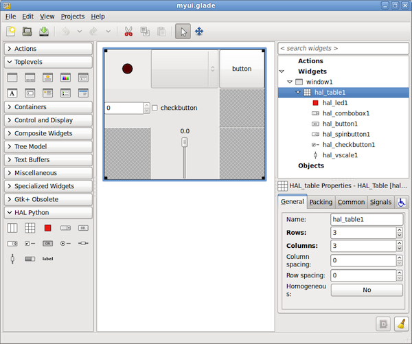
Select File→Save as, give it a name like myui.ui and make sure it’s saved as GtkBuilder file (radio button left bottom corner in Save dialog). The convention for GtkBuilder file extension is .ui. You can now run it with:
gladevcp myui.ui
1.2. Integrating the example UI into Axis
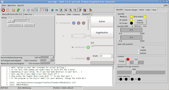
While you could run your UI as a separate top level window side-by-side with Axis, having it within the Axis frame as a tab side-by-side with the Preview and DRO tabs is more elegant. To do so, edit your .ini file and add two variables to the DISPLAY section of ini file:
Try it out by running Axis - there should be a new tab called GladeVCP near the DRO tab. Select that tab, you should see the example panel nicely fit within Axis like so:
1.3. Integrating into Touchy
Touchy also understands EMBED_TAB_NAME/EMBED_TAB_COMMAND variables from INI file so instructions for it are equal to Axis.
1.4. Axis: linking HAL pins in the example UI
To be useful, the pins in your UI need to be linked to the rest of your setup. Usually this is done by running one or several HAL files through the HALFILE and POSTGUI_HALFILE statements in the HAL section of your .ini file.
For gladevcp components this not currently possible because all of these HALFILE statements are run before gladevcp is started, so linking to your UI’s pins from there would refer to pins which do not yet exist. You therefore need to prepare a file of all HAL commands which refer to / link with your UI’s pins and pass it to the gladevcp command in the EMBED_TAB_COMMAND statement like so:
EMBED_TAB_COMMAND = gladevcp -c gladevcp-test -H gladevcp-test.hal -w
There is an example gladevcp-test.hal file in the emc2-dev/lib/python/gladevcp directory. Before using it in the EMBED_TAB_NAME statement, make sure the loadusr statements at the top are commented out.
1.5. Adding custom user callbacks in Python
This is just a very minimal example to convey the idea - for a detailed description on how to program a gladevcp application, see GladeVCPprogramming and HalWidgets.
gladevcp cannot only manipulate or display HAL pins, you can also write regular event handlers in Python. This could be used, among others, to execute MDI commands. Here’s how you do it:
Write a Python module like so and save as e.g. handlers.py:
nhits = 0
def on_button_press(gtkobj,data=None):
global nhits nhits += 1 gtkobj.set_label("hits: %d" % nhits)
In glade, define a button or HAL button, select the Signals tab, and in the GtkButton properties select the pressed line. Enter on_button_press there, and save the glade file.
Then add the option -u handlers.py to the gladevcp command line. If your event handlers are spread over several files, just add multiple -u <pyfilename> options.
Now, pressing the button should change its label since it’s set in the callback function.
What the -u flag does is: all Python functions in this file are collected and setup as potential callback handlers for your Gtk widgets - they can be referenced from glade Signals tabs. The callback handlers are called with the particular object instance as parameter, like the GtkButton instance above, so you can apply any GtkButton method from there.
Or do some more useful stuff, like calling an MDI command!
1.6. Gladevcp command line options
See also man gladevcp . This is the usage message when you run gladevcp -h:
Usage: gladevcp [options] myfile.ui
Options:
- -h, --help
-
show this help message and exit
- -c NAME
-
Set component name to NAME. Default is base name of UI file
- -d
-
Enable debug output
- -g GEOMETRY
-
Set geometry WIDTHxHEIGHT+XOFFSET+YOFFSET.Values are in pixel units, XOFFSET/YOFFSET is referenced from top left of screen use -g WIDTHxHEIGHT for just setting size or -g +XOFFSET+YOFFSET for just position -H FILE execute hal statements from FILE with halcmd after the component is set up and ready
- -x XID
-
Re-parent gladevcp into an existing window XID instead of creating a new top level window
- -u FILE
-
Use File’s as additional user defined modules with handlers
- -U USEROPT
-
pass USEROPTs to Python modules
1.7. Troubleshooting
-
make sure your have the development version of emc2 installed. You don’t need the axisrc file any more, this was mentioned in the old GladeVcp wiki page.
-
run gladevcp or Axis from a terminal window. If you get Python errors, check whether there’s still a /usr/lib/python2.6/dist-packages/hal.so file lying around besides the newer /usr/lib/python2.6/dist-packages/_hal.so (note underscore); if yes, remove the hal.so file. It has been superseded by hal.py in the same directory and thus creates confusion.
-
if you’re using run-in-place, do a make clean to remove any accidentially left over hal.so file, then make.
-
if you’re using HAL_table or HAL_HBox widgets, be aware they have an HAL pin associated with it which is off by default. This pin controls whether these container’s children are active or not.
2. GladeVCP Programming
2.1. PyVCP to GladeVCP
Stock gladevcp can be used pretty much in the style of PyVCP - the major difference being that in the case of gladevcp, the glade user interface editor is used to design a screen layout, whereas PyVCP is driven by manually edited XML files. Also, PyVCP uses the TkInter widgets, whereas gladevcp uses the much richer GTK toolkit. Both support HAL widgets - widgets with one or more associated HAL pin which is the interface to the rest of EMC. Stock gladevcp and PyVCP panels are really just a bunch of virtual switches, dials, leds an so forth, wired to the outside world through the HAL layer, designed to set and read ints, bits and floats values.
Most widget sets, and their associated user interface editors, support the concept of callbacks - functions in user-written code which are executed when something happens in the UI - events like mouse clicks, characters typed, mouse movement, timer events, window hiding and exposure and so forth. Both PyVCP and stock gladevcp mainly do two things: mapping events on HAL widgets to actions like a value change of the associated HAL pin, and in the other direction - detecting if HAL pin values changed and updating the associated widget, like a LED, a meter, a bar, or just some label displaying a value. However, neither PyVCP nor stock gladevcp provide support for other actions than changing HAL values. Doing something more complex, like executing MDI commands to call a G-code subroutine, is outside scope.
2.2. Hal Widgets
GladeVcp includes a collection of Gtk widgets with attached HAL pins called HAL Widgets, intended to control, display or otherwise interact with the EMC HAL layer. They are intended to be used with the glade user interface editor. With proper installation, the HAL Widgets should show up in glade’s HAL Python widget group. Many HAL specific fields in the glade General section have an associated mouse-over tool tip.
HAL signals come in two variants, bits and numbers. Bits are off/on signals. Numbers can be "float", "s32" or "u32". For more information on HAL data types see the [→] section. The GladeVcp widgets can either display the value of the signal with an indicator widget, or modify the signal value with a control widget. Thus there are four classes of GladeVcp widgets that you can connect to a HAL signal. Another class of helper widgets allow you to organize and label your panel.
-
Widgets for indicating "bit" signals: HAL_LED
-
Widgets for controlling "bit" signals: HAL_Button, HAL_RadioButton, HAL_CheckButton, HAL_RadioButton
-
Widgets for indicating "number" signals: HAL_Label, HAL_ProgressBar, HAL_Bar, HAL_VBar, HAL_Meter
-
Widgets for controlling "number" signals: HAL_SpinButton, HAL_HScale, HAL_VScale
-
Helper widgets: HAL_Table, HAL_HBox
-
Tool Path preview: HAL_Gremlin
HAL Widgets inherit methods, properties and signals from the underlying Gtk widgets, so it is helpful to consult the Gtk and PyGTK documentation as well.
2.2.1. Widget and HAL pin naming
Most HAL widgets have a single associated HAL pin with the same name as the widget (glade: General→Name). Exceptions to this rule currently are the HAL_Spinbutton, which has two pins: a <widgetname>-f (float) and a <widgetname>-s (s32) pin, and the HAL_ProgressBar, which has a <widgetname> value input pin, and a <widgetname>.scale input pin.
2.2.2. Setting pin and widget values
As a general rule, if you need to set a HAL output widget’s value from Python code, do so by calling the underlying Gtk setter (e.g. set_active(), set_value()) - do not try to set the associated pin’s value by halcomp[pinname] = value directly because the widget will not notice.
It might be tempting to set HAL widget input pins programmatically. Note this defeats the purpose of an input pin in the first place - it should be linked to, and react to signals generated by other HAL components. While there is currently no write protection on writing to input pins in HAL Python, this doesn’t make sense. You might use setp pinname value in the associated halfile for testing though.
It is perfectly OK to set an output HAL pin’s value with halcomp[pinname] = value provided this HAL pin is not associated with a widget, that is, has been created by the hal_glib.GPin(halcomp.newpin(<name>,<type>,<direction>) method (see GladeVCProgramming for an example).
2.2.3. The hal-pin-changed signal
Event-driven programming means that the UI tells you when "something happens" - through a callback, like when a button was pressed. The output HAL widgets (those which display a HAL pin’s value) like LED, Bar, VBar, Meter etc, support the hal-pin-changed signal which may cause a callback into your Python code when - well, a HAL pin changes its value. This means there’s no more need for permanent polling of HAL pin changes in your code, the widgets do that in the background and let you know. The example in configs/gladevcp/examples/complex shows how this is handled in Python.
Here is an example how to set a hal-pin-changed signal for a HAL_LED in the glade UI editor:
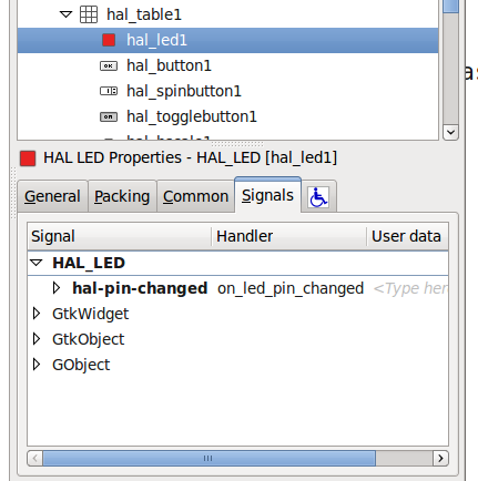
2.2.4. Buttons
This group of widget is derived from various Gtk buttons and consists of HAL_Button, HAL_ToggleButton, HAL_RadioButton and CheckButton widgets. All of them have a single output BIT pin named identical to the widget. Buttons have no additional properties compared to their base Gtk classes.
-
HAL_Button: instantaneous action, does not retain state. Important signal: pressed
-
HAL_ToggleButton, HAL_CheckButton: retains on/off state. Important signal: toggled
-
HAL_RadioButton: a one-of-many group. Important signal: toggled (per button).
-
Important common methods: set_active(), get_active()
-
Important properties: label, image
![]image::images/radiobutton.png[](gui/images/checkbutton.png)
Hint: Defining radio button groups in glade:
-
decide on default active button
-
in the other button’s General→Group select the default active button’s name in the Choose a Radio Button in this project dialog.
See configs/gladevcp/by-widget/radiobutton for a gladevcp application and UI file for working with radio buttons.
2.2.5. Scales
HAL_HScale and HAL_VScale are derived from the GtkHScale and GtkVScale respectively. They have one output FLOAT pin with name equal to widget name. Scales have no additional properties.

Hint: To make a scale useful in glade, add an Adjustment (General→Adjustment→New or existing adjustment) and edit the adjustment object. It defines the default/min/max/increment
values. Also, set adjustment Page size and Page increment to zero to avoid warnings.
2.2.6. SpinButton
HAL SpinButton is derived from GtkSpinButton and holds two pins:
Hint: to be useful, Spinbuttons need an adjustment value like scales, see above.
2.2.7. Label
HAL_Label is simple widget based on GtkLabel which represents a HAL pin value in a user-defined format. The pin’s HAL type depends on the label_pin_type property (0:S32, 1:float, 2:U32), see also the tooltip on General→HAL pin type (note this is different from PyVCP which has three label widgets, one for each type).
The text displayed depends on the text_template property - an Python format string to represent the pin value. It defaults to "%s" (values are converted by the str() function) but may contain anything legit in a as argument to Pythons format() method.
Example: Distance: %.03f will display the text and the pin value with 3 fractional digits padded with zeros for a FLOAT pin.
2.2.8. Containers: HAL_HBox and HAL_Table
Compared to their Gtk counterparts they have one input BIT pin which controls if their child widgets are sensitive or not. If the pin is low then child widgets are inactive which is the default.
Hint: if you find some part of your gladevcp application is grayed out (insensitive), see whether a container’s pin is unset.
2.2.9. LED
The HAL_Led simulates a real indicator LED . It has a single input BIT pin which controls it’s state: ON or OFF. Leds have several properties which control their look and feel:
-
on_color: a String defining ON color of led. May be any valid gtk.gdk.Color name. Not working on Ubuntu 8.04.
-
off_color: String defining OFF color of led. May be any valid gtk.gdk.Color name or special value "dark". "dark" means that OFF color will be set to 0.4 value of ON color. Not working on Ubuntu 8.04.
-
pick_color_on, pick_color_off: Colors for ON and OFF states may be represented as #RRRRGGGGBBBB strings. These are optional properties which have precedence over "on_color" and "off_color".
-
led_size: LED radius (for square - half of LED’s side)
-
led_shape: LED Shape. Valid values are 0 for round, 1 for oval and 2 for square shapes.
-
led_blink_rate: if set and led is ON then it’s blinking. Blink frequency is equal to "led_blink_rate" specified in milliseconds.
As an input widget, LED also supports the hal-pin-changed signal. If you want to get a notification in your code when the LED’s HAL pin was changed, then connect this signal to a handler, for example on_led_pin_changed and provide the handler as follows:
def on_led_pin_changed(self,hal_led,data=None):
print "on_led_pin_changed() - HAL pin value:",hal_led.hal_pin.get()
This will be called at any edge of the signal and also during program start up to report the current value.
Example LEDs:
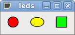
2.2.10. ProgressBar
Note: This widget might go away. Use the HAL_HBar and HAL_VBar widgets instead.
The HAL_ProgressBar is derived from gtk.ProgressBar and has two float HAL input pins:
-
<widgetname> - the current value to be displayed
-
<widgetname>.scale - the maximum absolute value of input
It has the following properties:
-
scale - value scale. set maximum absolute value of input. Same as setting the <widgetname>.scale pin. A float, range from -224 to 224.
-
green_limit - green zone limit lower limit
-
yellow_limit - yellow zone limit lower limit
-
red_limit - red zone limit lower limit
-
text_template - Text template to display the current value of the <widgetname> pin. Python formatting may be used for dict {"value":value}

2.2.11. ComboBox
HAL_ComboBox is derived from gtk.ComboBox. It enables choice of a value from a dropdown list.
It exports two HAL pins:
-
<widgetname>-f: the current value, type FLOAT
-
<widgetname>-s: the current value, type S32
It has the following property which can be set in glade:
column: the column index, type S32, defaults to -1, range from -1..100 .
In default mode this widgets sets the pins to the index of the chosen list entry. So if your widget has three labels, it may only assume values 0,1 and 2.
In column mode (column > -1), the value reported is chosen from the ListStore array as defined in Glade. So typically your widget definition would have two columns in the ListStore , one with text displayed in the dropdown, and an int or float value to use for that choice.
There’s an example in configs/gladevcp/by-widget/combobox/combobox.{py,ui} which uses column mode to pick a float value from the ListStore.
If you’re confused like me about how to edit ComboBox ListStores and CellRenderer , see http://www.youtube.com/watch?v=Z5_F-rW2cL8.
2.2.12. Bars
HAL Bar and VBar widgets for horizontal and vertical bars representing float values. They have one input FLOAT hal pin. Both bars have the following properties:
-
invert: Swap min and max direction. An inverted HBar grows from right to left, an inverted VBar from top to bottom.
-
min, max: Minimum and maximum value of desired range. It is not an error condition if the current value is outside this range.
-
zero: Zero point of range. If it’s inside of min/max range then the bar will grow from that value and not from the left (or right) side of the widget. Useful to represent values that may be both positive or negative.
-
force_width, force_height: Forced width or height of widget. If not set then size will be deduced from packing or from fixed widget size and bar will fill whole area.
-
text_template: Like in Label sets text format for min/max/current values. Can be used to turn off value display.
-
bg_color: Background (inactive) color of bar.
-
z0_color, z1_color, z2_color: Colors of different value zones. Defaults are "green", "yellow" and "red". For description of zones see "z*_border" properties.
-
* z0_border, z1_border: Define up bounds of color zones. By default only one zone is enabled. If you want more then one zone set "z0_border" and "z1_border" to desired values so zone 0 will fill from 0 to first border, zone 1 will fill from first to second border and zone 2 — from last border to 1. Borders are set as fractions, values from 0 to 1.
Examples:
![]image::images/vscale.png[](gui/images/hal_hbar.png)
2.2.13. Meter
HAL Meter is widget like PyVCP meter representing float value. It have one input FLOAT hal pin. Widget has following properties:
-
min, max: Minimum and maximum value of desired range. It is not an error condition if the current value is outside this range.
-
force_size: Forced diameter of widget. If not set then size will be deduced from packing or from fixed widget size and meter will fill all available space with respect to aspect ratio.
-
text_template: Like in Label sets text format for current value. Can be used to turn off value display.
-
label: Large label above center of meter.
-
sublabel: Small label below center of meter.
-
bg_color: Background color of meter.
-
z0_color, z1_color, </t>z2_color</tt>: Colors of different value zones. Defaults are "green", "yellow" and "red". For description of zones see "z*_border" properties.
-
z0_border, z1_border: Define up bounds of color zones. By default only one zone is enabled. If you want more then one zone set "z0_border" and "z1_border" to desired values so zone 0 will fill from min to first border, zone 1 will fill from first to second border and zone 2 — from last border to max. Borders are set as values in range min-max.
Examples:
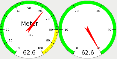
2.2.14. Gremlin tool path preview for .ngc files
Gremlin is a plot preview widget similar to the Axis preview window. It assumes a running EMC environment like Axis or Touchy. To connect to it, inspects the INI_FILE_NAME environment variable. Gremlin displays the current .ngc file - it does monitor for changes and reloads the ngc file if the file name in Axis/Touchy changes. If you run it in a gladevcp application when EMC is not running you might get a traceback because the Gremlin widget cant find EMC status, like the current file name.
Gremlin does not export any HAL pins. It has the following properties:
-
view : may be any of x, y, z, p (perspective) . Defaults to z view.
-
enable_dro : boolean; wether to draw a DRO on the plot or not. Defaults to True.
Example:
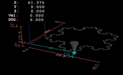
2.3. Action Widgets
GladeVcp includes a collection of "canned actions" called EMC Action Widgets for the glade user interface editor. Other than HAL widgets, which interact with HAL pins, EMC Actions interact with EMC and the G-code interpreter.
EMC Action Widgets are derived from the Gtk.Action widget. The Action widget in a nutshell:
-
it is an object available in glade
-
it has no visual appearance by itself
-
it’s purpose: associate a visible, sensitive UI component like menu, toolbutton, button with a command. See these widget’s General→Related Action property.
-
the "canned action" will be executed when the associated UI component is triggered (button press, menu click..)
-
it provides an easy way to execute commands without resorting to Python programming.
The appearance of EMC Actions in glade is roughly as follows:
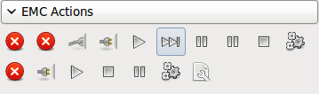
Tooltip hovers provide a description.
2.3.1. Action widget types
EMC Action widgets
These are one-shot type widgets. They implement a single action and are for use in simple buttons, menu entries or radio/check groups.
EMC ToggleAction widgets
These are bi-modal widgets. They implement two actions or use a second (usually pressed) state to indicate that currently an action is running. Toggle actions are aimed for use in ToggleButtons, ToggleToolButtons or toggling menu items. A simplex example is the ESTOP toggle button.
Currently the following widgets are available:
-
The ESTOP toggle sends ESTOP or ESTOP_RESET commands to EMC depending on it’s state.
-
The ON/OFF toggle sends STATE_ON and STATE_OFF commands.
-
Pause/Resume sends AUTO_PAUSE or AUTO_RESUME commands.
The following toggle actions have only one associated command and use the pressed state to indicate that the requested operation is running:
-
The Run toggle sends an AUTO_RUN command and waits in the pressed state until the interpreter is idle again.
-
The Stop toggle is inactive until the interpreter enters the active state (is running G-code) and then allows user to send AUTO_ABORT command.
-
The MDI toggle sends given MDI command and waits for its completion in pressed inactive state.
The Action_MDI Toggle and Action_MDI widgets
These widgets provide a means to execute arbitrary MDI commands.
A simple example: Execute MDI command on button press
Here’s a glade UI file which conveys the basics:
Open it in glade and study how it’s done. Start Axis, and then start this from a terminal window with gladevcp whoareyou.ui . See the hal_action_mdi1 Action and it’s MDI command property - this just executes (MSG, "Hi, I’m an EMC_Action_MDI") so there should be a message popup in Axis like so:
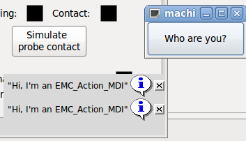
You’ll notice that the button associated with the Action_MDI action is grayed out if the machine is off, in E-Stop or the program is running. It will automatically become active when the machine is turned on and out of E-Stop, and the program is idle.
Parameter processing in the Action_MDI and ToggleAction_MDI widgets
Optionally, MDI command strings may have parameters substituted before they are passed to the interpreter. Parameters currently may be names of HAL pins in the gladevcp component (in a later release, this will be extended to cover HAL pins of other components as well). This is how it works:
-
assume you have a HAL SpinBox named speed, and you want to pass it’s current value as a parameter in an MDI command.
-
The HAL SpinBox? will have a float-type HAL pin named speed-f (see HalWidgets description).
-
To substitute this value in the MDI command, insert the HAL pin name
-
for the above HAL SpinBox, we could use (MSG, "The speed is:
Here’s the example UI file for gladevcp: , and here’s what you get:
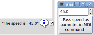
An advanced example: Feeding parameters to an O-word subroutine
It’s perfectly OK to call an O-word subroutine in an MDI command, and pass HAL pin values as actual parameters. Here’s an example UI file upload:owordsub.ui and O-word sub:
Place oword.ngc so Axis can find it, and run gladevcp owordsub.ui from a terminal window. This looks like so:
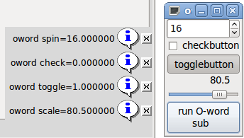
Preparing for an MDI Action, and cleaning up afterwards
The EMC G-Code interpreter has a single global set of variables, like feed, spindle speed, relative/absolute mode and others. If you use G code commands or O-word subs, some of these variables might get changed by the command or subroutine - for example, a probing subroutine will very likely set the feed value quite low. With no further precautions, your previous feed setting will be overwritten by the probing subroutine’s value.
To deal with this surprising and undesirable side effect of a given O-word subroutine or G-code statement executed with an EMC ToggleAction_MDI, you might associate pre-MDI and post-MDI handlers with a given EMC ToggleAction_MDI. These handlers are optional and provide a way to save any state before executing the MDI Action, and to restore it to previous values. The signal names are mdi-command-start and mdi-command-stop; the handler names can be set in glade like any other handler.
Here’s an example how a feed value might be saved and restored by such handlers (note that EMC command and status channels are available as self.emc and self.stat through the _EMC_ActionBase class:
def on_mdi_command_start(self, action, userdata=None):
    action.stat.poll()
    self.start_feed = action.stat.settings[1]
def on_mdi_command_stop(self, action, userdata=None):
    action.emc.mdi('F%.1f' % (self.start_feed))
    while action.emc.wait_complete() == -1:
        pass
Only the Action_MDI Toggle widget supports these signals.
Using the EMC Stat object to deal with status changes
Many actions depend on EMC status - is it in manual, MDI or auto mode? is a program running, paused or idle? You cannot start an MDI command while a G-code program is running, so this needs to be taken care of. Many EMC actions take care of this themselves, and related buttons and menu entries are deactivated when the operation is currently impossible.
When using Python event handlers - which are at a lower level than Actions - one needs to take care of dealing with status dependencies oneself. For this purpose, there’s the EMC Stat widget: to associate EMC status changes with event handlers.
EMC Stat has no visible component - you just add it to your UI with glade. Once added, you can associate handlers with its following signals:
-
state-related: "state-estop", "state-estop-reset", "state-on", "state-off" - emitted when E-Stop condtion occurs, is reset, machine is turned on, or is turned off
-
mode-related: "mode-manual", "mode-mdi", "mode-auto" - emitted when EMC enters that particular mode
-
interpreter-related: "interp-run", "interp-idle", "interp-paused", "interp-reading", "interp-waiting" - emitted when the G-code interpreter changes into that mode
2.4. User Defined Actions
As most of the infrastructure to support user-defined actions in glade and the GTK widget set is in place, the new gladevcp version really just provides a way for the user to write a Python module whose class methods - or in the simple case, just functions - can be referred to in glade as event handlers, a way to import this module(s) into gladevcp at runtime and properly link it with the rest of the HAL layer.
2.4.1. HAL value change events
We also extended the way the HAL input pins interact with the gladevcp panel. Beyond HAL widgets displaying pin values, there is now a way to attach a value-changed callback to a HAL pin, which fits nicely with the event-driven structure of a typical widget application: every activity, be it mouse click, key, timer expired, or the change of a HAL pin’s value, generates a callback and is handled by the same orthogonal mechanism.
Note that the above refers to explicitly declared HAL pins. HAL widgets come with a pre-defined signal hal-pin-changed, see the HalWidgets page for details.
See the Adding HAL pins section below for details.
2.4.2. Persistent values in GladeVCP
A annoying aspect of gladevcp in its earlier form and pyvcp is the fact that you may change values through text entry, sliders, spin boxes, toggle buttons etc, but their settings are not saved and restored at the next run of EMC - they start at the default value as set in the panel or widget definition. Therefore I added an easy-to-use mechanism to save and restore the state of HAL widgets, and program variables (in fact instance attributes) as well. This mechanism uses the popular .ini file syntax and has safeguards against the .ini file and the corresponding user interface or program variables getting out of sync - just imagine renaming, adding or deleting widgets in glade: an .ini file lying around from a previous program version, or an entirely different user interface, would be not be able to restore the state properly. This situation is detected through a signature which depends on all object names and types which are saved and to be restored. In the case of signature mismatch, a new .ini file with default settings is generated.
2.4.3. Programming model
The overall protocol is as follows:
-
design your UI with glade, and set signal handlers where you want actions associated with a widget
-
write a Python module which contains callable objects (see handler models below)
-
pass your module’s path name to gladevcp with the -u <module> option
-
gladevcp imports the module, inspects it for signal handlers and connects them to the widget tree
-
the main event loop is run.
The simple handler model
For simple tasks it’s sufficient to define functions named after the glade signal handlers. These will be called when the corresponding event happens in the widget tree. Here’s a trivial example - it assumes that the pressed signal of a GTK Button or HAL Button is linked to a callback called on_button_press:
nhits = 0
def on_button_press(gtkobj,data=None):
global nhits
nhits += 1
gtkobj.set_label("hits: %d" % nhits)
Add this function to a Python file and run as follows:
gladevcp -u <myhandler>.py mygui.ui
Note communication between handlers has to go through global variables, which does not scale well and is positively un-pythonic. This is why we came up with the class-based handler model.
The class-based handler model
The idea here is: handlers are linked to class methods. The underlying class(es) are instantiated and inspected during gladevcp startup and linked to the widget tree as signal handlers. So the task now is to write:
-
one or more several class definition(s) with one or several methods, in one module or split over several modules,
-
a function get_handlers in each module which will return a list of class instances to gladevcp - their method names will be linked to signal handlers
Here is a minimum user-defined handler example module:
Class MyCallbacks :
def on_this_signal(self,obj,data=None):
print "this_signal happened, obj=",obj
def get_handlers(halcomp,builder,useropts):
return [MyCallbacks ()]
Now, on_this_signal will be available as signal handler to your widget tree.
The get_handlers protocol
If during module inspection gladevcp finds a function get_handlers, it calls it as follows:
get_handlers(halcomp,builder,useropts)
the arguments are:
-
halcomp - refers to the HAL component under construction
-
builder - widget tree - result of reading the UI definition (either referring to a GTKBuilder or libglade-type object)
-
useropts - a list of strings collected from the gladevcp command line -U <useropts> option
gladevcp then inspects the list of class instances and retrieves their method names. Qualifying method names are connected to the widget tree as signal handlers. Only method names which do not begin with an _ (underscore) are considered.
Note that regardless whether you’re using the libglade or the new GtkBuilder format for your glade UI, widgets can always be referred to as builder.get_object(<widgetname>). Also, the complete list of widgets is available as builder.get_objects() regardless of UI format.
2.4.4. Initialization sequence
It is important to know in which state of affairs your get_handlers() function is called so you know what is safe to do there and what not. First, modules are imported and initialized in command line order. After successful import, get_handlers() is called in the following state:
-
the widget tree is created, but not yet realized (no toplevel window.show() has been executed yet)
-
the halcomp HAL component is set up and all HAL widget’s pins have already been added to it
-
it is safe to add more HAL pins because halcomp.ready() has not yet been called at this point, so you may add your own pins, for instance in the class init() method.
Once all modules have been imported and method names extracted, the following steps happen:
-
all qualifying method names will be connected to the widget tree with connect_signals()/signal_autoconnect() (depending on the type of UI imported - GtkBuilder vs the old libglade format).
-
the HAL component is finalized with halcomp.ready()
-
if a window ID was passed as argument, the widget tree is re-parented to run in this window, and glade’s toplevel window1 is abandoned (see FAQ)
-
if a HAL command file was passed with -H halfile, it is executed with halcmd
-
the gtk main loop is run.
So when your handler class is initialized, all widgets are existent but not yet realized (displayed on screen). And the HAL component isn’t ready as well, so its unsafe to access pins values in your init() method.
If you want to have a callback to execute at program start after it is safe to access HAL pins, then a connect a handler to the realize signal of the top level window1 (which might be its only real purpose). At this point gladevcp is done with all setup tasks, the halfile has been run, and gladevcp is about to enter the gtk main loop.
2.4.5. Multiple callbacks with the same name
Within a class, method names must be unique. However, it is OK to have multiple class instances passed to gladevcp by get_handlers() with identically named methods. When the corresponding signal occurs, these methods will be called in definition order - module by module, and within a module, in the order class instances are returned by get_handlers().
2.4.6. The gladevcp -U <useropts> flag
Instead of extending gladevcp for any conceivable option which could potentially be useful for a handler class, you may use the -U <useroption> flag (repeatedly if you wish). This flag collects a list of <useroption> strings. This list is passed to the get_handlers() function (useropts argument). Your code is free to interpret these strings as you see fit. An possible usage would be to pass them to the Python exec function in your get_handlers() as follows:
debug = 0
...
def get_handlers(halcomp,builder,useropts):
...
global debug # assuming there's a global var
for cmd in useropts:
exec cmd in globals()
This way you can pass arbitrary Python statements to your module through the gladevcp -U option, for example:
gladevcp -U debug=42 -U "print debug=%d % debug" …
This should set debug to 2 and confirm that your module actually did it.
2.4.7. Persistence
If you want any of: GTK widget state, HAL widgets output pin’s values and/or class attributes of your handler class to be retained across invocations, proceed as follows:
-
import the gladevcp.persistence module
-
decide which instance attributes, and their default values you want to have retained, if any
-
decide which widgets should have their state retained
-
describe these decisions in your handler class' init() method through a nested dictionary as follows:
def __init__(self, halcomp,builder,useropts):
self.halcomp = halcomp
self.builder = builder
self.useropts = useropts
self.defaults = {
    # the following names will be saved/restored as method attributes
    # the save/restore mechanism is strongly typed - the variables type will be derived from the type of the
    # initialization value. Currently supported types are: int, float, bool, string
    IniFile.vars : { 'nhits' : 0, 'a': 1.67, 'd': True ,'c' : "a string"},
    # to save/restore all widget's state which might remotely make sense, add this:
    IniFile.widgets : widget_defaults(builder.get_objects())
    # a sensible alternative might be to retain only all HAL output widgets' state:
    # IniFile.widgets: widget_defaults(select_widgets(self.builder.get_objects(), hal_only=True,output_only = True)),
}
and associate an .ini file with this descriptor:
self.ini_filename = __name__ + '.ini'
self.ini = IniFile(self.ini_filename,self.defaults,self.builder)
self.ini.restore_state(self)
after restore_state(), self will have attributes set if as running the following:
self.nhits = 0
self.a = 1.67
self.d = True
self.c = "a string"
Note that types are saved and preserved on restore. This example assumes that the ini file didn’t exist or had the default values from self.defaults.
After this incantation, you can use the following IniFil methods:
-
ini.save_state(obj) - saves objs’s attributes as per IniFil.vars dictionary and the widget state as described in IniFile.widgets in self.defaults
-
ini.create_default_ini() - create a .ini file with default values
-
ini.restore_state(obj) - restore HAL out pins and obj’s attributes as saved/initialized to default as above
To save the widget and/or variable state on exit, connect a signal handler to the window1 (toplevel) destroy event:
def on_destroy(self,obj,data=None):
    self.ini.save_state(self)
Next time you start the gladevcp application, the widgets should come up in the state when the application was closed.
2.4.8. Hand-editing .ini files
You can do that, but note that the values in self.defaults override your edits if there is a syntax or type error in your edit. The error is detected, a console message will hint about that happened, and the bad inifile will be renamed to have the .BAD suffix. Subsequent bad ini files overwrite earlier .BAD files.
2.4.9. Adding HAL pins
If you need HAL pins which are not associated with a specific HAL widget, add them as follows:
import hal_glib
...
# in your handler class __init__():
self.example_trigger = hal_glib.GPin(halcomp.newpin('example-trigger', hal.HAL_BIT, hal.HAL_IN))
To get a callback when this pin’s value changes, associate a value-change callback with this pin, add:
self.example_trigger.connect('value-changed', self._on_example_trigger_change)
and define a callback method (or function, in this case leave out the self parameter):
# note '_' - this method will not be visible to the widget tree
def _on_example_trigger_change(self,pin,userdata=None):
print "pin value changed to:" % (pin.get())
2.4.10. Adding timers
Since gladevcp uses GTK widgets which rely on the GObject base class, the full glib functionally is available. Here is an example for a timer callback:
def _on_timer_tick(self,userdata=None):
...
return True # to restart the timer; return False for on-shot
...
# demonstrate a slow background timer - granularity is one second
# for a faster timer (granularity 1msec), use this:
# glib.timeout_add(100, self._on_timer_tick,userdata) # 10Hz
glib.timeout_add_seconds(1, self._on_timer_tick)
2.4.11. Implementation note: Key handling in Axis
We believe key handling works OK, but since it is new code, we’re telling about it you so you can watch out for problems; please let us know of errors or odd behavior. This is the story:
Axis uses the TkInter widget set. GladeVCP applications use Gtk widgets and run in a separate process context. They are hooked into Axis with the Xembed protocol. This allows a child application like gladevcp to properly fit in a parent’s window, and - in theory - have integrated event handling.
However, this assumes that both parent and child application properly support the Xembed protocol, which Gtk does, but TkInter doesn’t. A consequence of this is that certain keys would not be forwarded from a gladevcp panel to Axis properly under all circumstances. One of these situations was the case when an Entry, or SpinButton widget had focus: in this case, for instance an Escape key would not have been forwarded to Axis and cause an abort as it should, with potentially disastrous consequences.
Therefore, key events in gladevcp are explicitly handled, and selectively forwarded to Axis, to assure that such situations cannot arise. For details, see the keyboard_forward() function in lib/python/gladevcp/xembed.py.
2.4.12. FAQ
-
I get an unexpected unmap event in my handler function right after startup. What’s this?: This is a consequence of your glade UI file having the window1 Visible property set to True, together with re-parenting the gladevcp window into Axis or touchy. The gladevcp widget tree is created, including a top level window, and then reparented into Axis, leaving that toplevel window laying around orphaned. To avoid having this useless empty window hanging around, it is unmapped (made invisible), which is the cause of the unmap signal you get. Suggested fix: set window1.visible to False, and ignore an initial unmap event.
-
my gladevcp program starts, but no window appears where I expect it to be?: The window Axis allocates for gladevcp will obtain the natural size of all its child widgets combined. It’s the child widget’s job to request a size (width and/or height). However, not all widgets do request a width greater than 0, for instance the Graph widget in its current form. If there’s such a widget in your glade file and it’s the one which defines the layout you might want to set its width explicitly. Note that setting the window1 width and height properties in glade does not make sense because this window will be orphaned during re-parenting and hence its geometry will have no impact on layout (see above). The general rule is: if you manually run a UI file with gladevcp <uifile> and its window has reasonable geometry, it should come up in Axis properly as well.
2.4.13. Examples, and rolling your own gladevcp application
Visit emc2/configs/gladevcp for running examples. The templates subdirectory has starters for your own projects.
HAL
1. Getting Started
1.1. Hal Commands
More detailed information can be found in the man page for halcmd "man halcmd" in a terminal window. To see the HAL configuration and check the status of pins and parameters use the HAL Configuration window on the Machine menu in AXIS. To watch a pin status open the Watch tab and click on each pin you wish to watch and it will be added to the watch window.
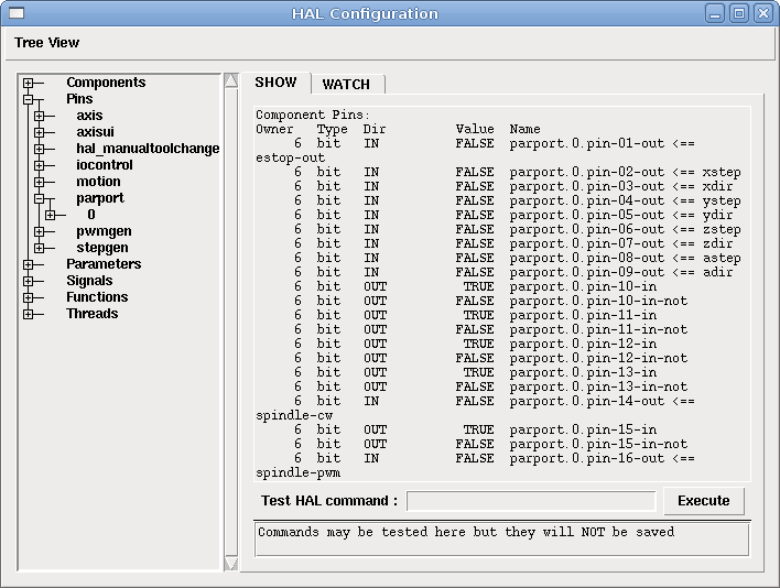
1.1.1. loadrt
The command "loadrt" loads a real time HAL component. Real time component functions need to be added to a thread to be updated at the rate of the thread. You cannot load a user space component into the real time space.
The syntax and an example:
loadrt <component> <options>
loadrt mux4 count=1
1.1.2. addf
The command "addf" adds a real time component function to a thread. You have to add a function from a HAL real time component to a thread to get the function to update at the rate of the thread.
If you used the Stepper Config Wizard to generate your config you will have two threads.
-
base-thread (the high-speed thread): this thread handles items that need a fast response, like making step pulses, and reading and writing the parallel port.
-
servo-thread (the slow-speed thread): this thread handles items that can tolerate a slower response, like the motion controller, ClassicLadder, and the motion command handler.
The syntax and an example:
addf <component> <thread>
addf mux4 servo-thread
1.1.3. loadusr
The command "loadusr" loads a user space HAL component. User space programs are their own separate processes, which optionally talk to other HAL components via pins and parameters. You cannot load real time components into user space.
Flags may be one or more of the following:
- -W
-
to wait for the component to become ready. The component is assumed to have the same name as the first argument of the command.
- -Wn <name>
-
to wait for the component, which will have the given <name>.
- -w
-
to wait for the program to exit
- -i
-
to ignore the program return value (with -w)
The syntax and examples:
loadusr <component> <options>
loadusr halui
loadusr -Wn spindle gs2_vfd -n spindle
in English it means "loadusr wait for name spindle component gs2_vfd name spindle."
1.1.4. net
The command "net" creates a "connection" between a signal and and one or more pins. If the signal does not exist net creates the new signal. This replaces the need to use the command newsig. The direction indicators "⇐ and ⇒" are only to make it easier for humans to follow the logic and are not used by the net command.
The syntax and an example:
net <signal-name> <pin-name> <opt-direction> <opt-pin-name>
net both-home-y <= parport.0.pin-11-in
Each signal can only have one source (a HAL "Dir out” pin) and as many readers (a HAL "Dir in" pin) as you like. In the Dir column of the HAL Configuration window you can see which pins are "in" and which are "out". The following figure shows the "direction" of the signal from the source, through the signal, and then out to the reader(s).
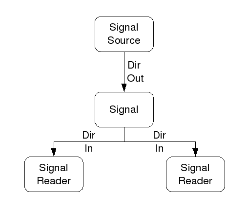
This example shows the signal xStep with the source being stepgen.0.out and with two readers, parport.0.pin-02-out and parport.0.pin-08-out. Basically the value of stepgen.0.out is send to the signal xStep and that value is then sent to parport.0.pin-02-out and parport.0.pin-08-out.
   signal    source            destination          destination
net xStep stepgen.0.out => parport.0.pin-02-out parport.0.pin-08-out
Since the signal xStep contains the value of stepgen.0.out (the source) you can use the same signal again to send the value to another reader. To do this just use the signal with the readers on another line.
net xStep <= stepgen.0.out => parport.0.pin-02-out
The so called I/O pins like index-enable do not follow this rule.
1.1.5. setp
The command "setp" sets the value of a pin or parameter. The valid values will depend on the type of the pin or parameter. It is an error if the data types do not match.
Some components have parameters that need to be set before use. Parameters can be set before use or while running as needed. You cannot use setp on a pin that is connected to a signal.
The syntax and an example:
setp <pin/parameter-name> <value>
setp parport.0.pin-08-out TRUE
1.1.6. unlinkp
The command "unlinkp" unlinks a pin from the connected signal. If no signal was connected to the pin prior running the command, nothing happens.
The syntax and an example:
unlinkp <pin-name>
unlinkp parport.0.pin-02-out
1.1.7. Obsolete Commands
linksp
The command "linksp" creates a "connection" between a signal and one pin.
The syntax and an example:
linksp <signal-name> <pin-name>
linksp X-step parport.0.pin-02-out
The "linksp" command has been superseded by the "net" command.
linkps
The command "linkps" creates a "connection" between one pin and one signal. It is the same as linksp but the arguments are reversed.
The syntax and an example:
linkps <pin-name> <signal-name>
linkps parport.0.pin-02-out X-Step
The "linkps" command has been superseded by the "net" command.
newsig
the command "newsig" creates a new HAL signal by the name <signame> and the data type of <type>. Type must be "bit", "s32", "u32" or "float". Error if <signame> all ready exists.
The syntax and an example:
newsig <signame> <type>
newsig Xstep bit
More information can be found in the HAL manual or the man pages for halrun.
1.2. Hal Data
1.2.1. Bit
A bit value is an on or off.
-
bit values = true or 1 and false or 0 (True, TRUE, true are all valid)
1.2.2. Float
A "float" is a floating point number. In other words the decimal point can move as needed.
-
float values = a 32 bit floating point value, with approximately 24 bits of resolution and over 200 bits of dynamic range.
For more information on floating point numbers see:
1.2.3. s32
An "s32" number is a whole number that can have a negative or positive value.
-
s32 values = integer numbers -2147483648 to 2147483647
1.2.4. u32
A "u32" number is a whole number that is positive only.
-
u32 values = integer numbers 0 to 4294967295
1.3. Hal Files
If you used the Stepper Config Wizard to generate your config you will have up to three HAL files in your config directory.
-
my-mill.hal (if your config is named "my-mill") This file is loaded first and should not be changed if you used the Stepper Config Wizard.
-
custom.hal This file is loaded next and before the GUI loads. This is where you put your custom HAL commands that you want loaded before the GUI is loaded.
-
custom_postgui.hal This file is loaded after the GUI loads. This is where you put your custom HAL commands that you want loaded after the GUI is loaded. Any HAL commands that use pyVCP widgets need to be placed here.
1.4. HAL Components
Two parameters are automatically added to each HAL component when it is created. These parameters allow you to scope the execution time of a component.
.time(((time))) +
.tmax(((tmax)))
Time is the number of CPU cycles it took to execute the function.
Tmax is the maximum number of CPU cycles it took to execute the function. Tmax is a read/write parameter so the user can set it to 0 to get rid of the first time initialization on the function’s execution time.
1.5. Logic Components
Hal contains several real time logic components. Logic components follow a "Truth Table" that states what the output is for any given input. Typically these are bit manipulators and follow electrical logic gate truth tables.
1.5.1. and2
The "and2" component is a two input "and" gate. The truth table below shows the output based on each combination of input.
Syntax
and2 [count=N] or [names=name1[,name2...]]
Functions
and2.n
Pins
and2.N.in0 (bit, in) +
and2.N.in1 (bit, in) +
and2.N.out (bit, out)
Truth Table
| in0 | in1 | out |
|---|---|---|
False |
False |
False |
True |
False |
False |
False |
True |
False |
True |
True |
True |
1.5.2. not
The "not" component is a bit inverter.
Syntax
not [count=n] or [names=name1[,name2...]]
Functions
not.all +
not.n
Pins
not.n.in (bit, in) +
not.n.out (bit, out)
Truth Table
| in | out |
|---|---|
True |
False |
False |
True |
1.5.3. or2
The "or2" component is a two input OR gate.
Syntax
or2[count=n] or [names=name1[,name2...]]
Functions
or2.n
Pins
or2.n.in0 (bit, in) +
or2.n.in1 (bit, in) +
or2.n.out (bit, out)
Truth Table
| in0 | in1 | out |
|---|---|---|
True |
False |
True |
True |
True |
True |
False |
True |
True |
False |
False |
False |
1.5.4. xor2
The "xor2" component is a two input XOR (exclusive OR)gate.
Syntax
xor2[count=n] or [names=name1[,name2...]]
Functions
xor2.n
Pins
xor2.n.in0 (bit, in) +
xor2.n.in1 (bit, in) +
xor2.n.out (bit, out)
Truth Table
| in0 | in1 | out |
|---|---|---|
True |
False |
True |
True |
True |
False |
False |
True |
True |
False |
False |
False |
1.5.5. Logic Examples
An "and2" example connecting two inputs to one output.
loadrt and2 count=1 +
addf and2.0 servo-thread +
net my-sigin1 and2.0.in0 <= parport.0.pin-11-in +
net my-sigin2 and2.0.in1 <= parport.0.pin-12-in +
net both-on parport.0.pin-14-out <= and2.0.out
In the above example one copy of and2 is loaded into real time space and added to the servo thread. Next pin 11 of the parallel port is connected to the in0 bit of the and gate. Next pin 12 is connected to the in1 bit of the and gate. Last we connect the and2 out bit to the parallel port pin 14. So following the truth table for and2 if pin 11 and pin 12 are on then the output pin 14 will be on.
1.6. Conversion Components
1.6.1. weighted_sum
The weighted_sum converts a group of bits to an integer. The conversion is the sum of the "weights" of the bits that are on plus any offset. This is similar to a binary coded decimal but with more options. The "hold" bit stops processing the input changes so the "sum" will not change.
The following syntax is used to load the weighted_sum component.
loadrt weighted_sum wsum_sizes=size[,size,...]
Creates weighted sum groups each with the given number of input bits (size).
To update the weighted_sum you need to attach process_wsums to a thread.
addf process_wsums servo-thread
This updates the weighted_sum component.
In the following example clipped from the HAL Configuration window in Axis the bits "0" and "2" are true and there is no offset. The "weight" of 0 is 1 and the "weight" of 2 is 4 so the sum is 5.
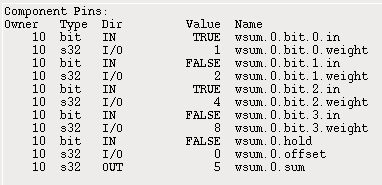
1.7. Halshow
The script halshow can help you find your way around a running HAL. This is a very specialized system and it must connect to a working HAL. It cannot run standalone because it relies on the ability of HAL to report what it knows of itself through the halcmd interface library. It is discovery based. Each time halshow runs with a different EMC configuration it will be different.
As we will soon see, this ability of HAL to document itself is one key to making an effective CNC system.
1.7.1. Starting Halshow
Halshow is in the AXIS menu under Machine/Show Hal Configuration.
Halshow is in the TkEMC menu under Scripts/Hal Show.
1.7.2. Hal Tree Area
At the left of its display as shown in figure [cap:Halshow-Layout] is a tree view, somewhat like you might see with some file browsers. At the right is a tabbed notebook with tabs for show and watch.
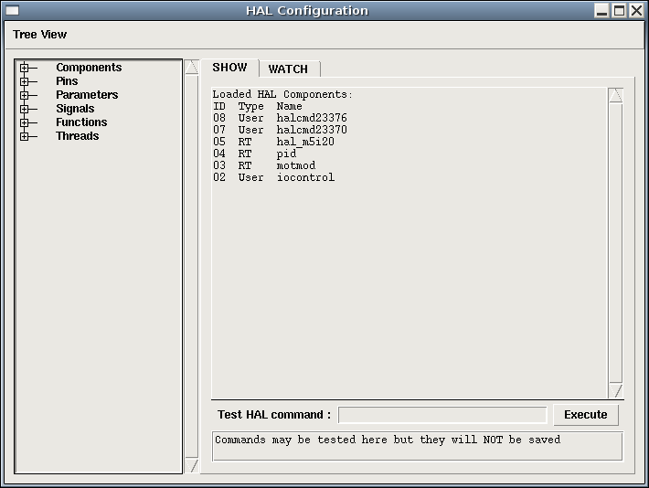
The tree shows all of the major parts of a HAL. In front of each is a small plus (+) or minus (-) sign in a box. Clicking the plus will expand that tree node to display what is under it. If that box shows a minus sign, clicking it will collapse that section of the tree.
You can also expand or collapse the tree display using the Tree View menu at the upper left edge of the display. Under Tree View you will find: Expand Tree, Collapse Tree; Expand Pins, Expand Parameters, Expand Signals; and Erase Watch. (Note that Erase Watch erases’all' previously set watches, you cannot erase just one watch.)
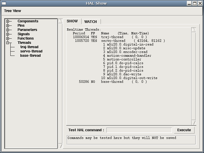
1.7.3. Hal Show Area
Clicking on the node name, the word "Components" for example, will show you (under the "Show" tab) all that hal knows about the contents of that node. Figure [cap:Halshow-Layout] shows a list exactly like you will see if you click the "Components" name while you are running a standard m5i20 servo card. The information display is exactly like those shown in traditional text based HAL analysis tools. The advantage here is that we have mouse click access, access that can be as broad or as focused as you need.
If we take a closer look at the tree display we can see that the six major parts of a HAL can all be expanded at least one level. As these levels are expanded you can get more focused with the reply when you click on the rightmost tree node. You will find that there are some hal pins and parameters that show more than one reply. This is due to the nature of the search routines in halcmd itself. If you search one pin you may get two, like this:
Component Pins: +
Owner Type Dir Value Name +
06 bit -W TRUE parport.0.pin-10-in +
06 bit -W FALSE parport.0.pin-10-in-not
The second pin’s name contains the complete name of the first.
Below the show area on the right is a set of widgets that will allow you to play with the running HAL. The commands you enter here and the effect that they have on the running HAL are not saved. They will persist as long as EMC remains up but are gone as soon as EMC is.
The entry box labeled "Test Hal Command:" will accept any of the commands listed for halcmd. These include:
-
loadrt, unloadrt (load/unload real-time module)
-
loadusr, unloadusr (load/unload user-space component)
-
addf, delf (add/delete a function to/from a real-time thread)
-
net (create a connection between two or more items)
-
setp (set parameter (or pin) to a value)
This little editor will enter a command any time you press <enter> or push the execute button. An error message from halcmd will show below this entry widget when these commands are not properly formed. If you are not certain how to set up a proper command you’ll need to read again the documentation on halcmd and the specific modules that you are working with.
Let’s use this editor to add a differential module to a hal and connect it to axis position so that we could see the rate of change in position, i.e., acceleration. We first need to load a hal module named blocks, add it to the servo thread, then connect it to the position pin of an axis. Once that is done we can find the output of the differentiator in halscope. So let’s go. (Yes, I looked this one up.)
loadrt blocks ddt=1
Now look at the components node and you should see blocks in there someplace.
Loaded HAL Components: +
ID Type Name +
10 User halcmd29800 +
09 User halcmd29374 +
08 RT blocks +
06 RT hal_parport +
05 RT scope_rt +
04 RT stepgen +
03 RT motmod +
02 User iocontrol
Sure enough there it is. Notice that its ID is 08. Next we need to find out what functions are available with it so we look at functions:
Exported Functions: +
Owner CodeAddr Arg FP Users Name +
08 E0B97630 E0DC7674 YES 0 ddt.0 +
03 E0DEF83C 00000000 YES 1 motion-command-handler +
03 E0DF0BF3 00000000 YES 1 motion-controller +
06 E0B541FE E0DC75B8 NO 1 parport.0.read +
06 E0B54270 E0DC75B8 NO 1 parport.0.write +
06 E0B54309 E0DC75B8 NO 0 parport.read-all +
06 E0B5433A E0DC75B8 NO 0 parport.write-all +
05 E0AD712D 00000000 NO 0 scope.sample +
04 E0B618C1 E0DC7448 YES 1 stepgen.capture-position +
04 E0B612F5 E0DC7448 NO 1 stepgen.make-pulses +
04 E0B614AD E0DC7448 YES 1 stepgen.update-freq
Here we look for owner #08 and see that blocks has exported a function named ddt.0. We should be able to add ddt.0 to the servo thread and it will do its math each time the servo thread is updated. Once again we look up the addf command and find that it uses three arguments like this:
addf <functname> <threadname> [<position>]
We already know the functname=ddt.0 so let’s get the thread name right by expanding the thread node in the tree. Here we see two threads, servo-thread and base-thread. The position of ddt.0 in the thread is not critical. So we add the function ddt.0 to the servo-thread:
addf ddt.0 servo-thread
This is just for viewing, so we leave position blank and get the last position in the thread. Figure [cap:Addf-Command] shows the state of halshow after this command has been issued.
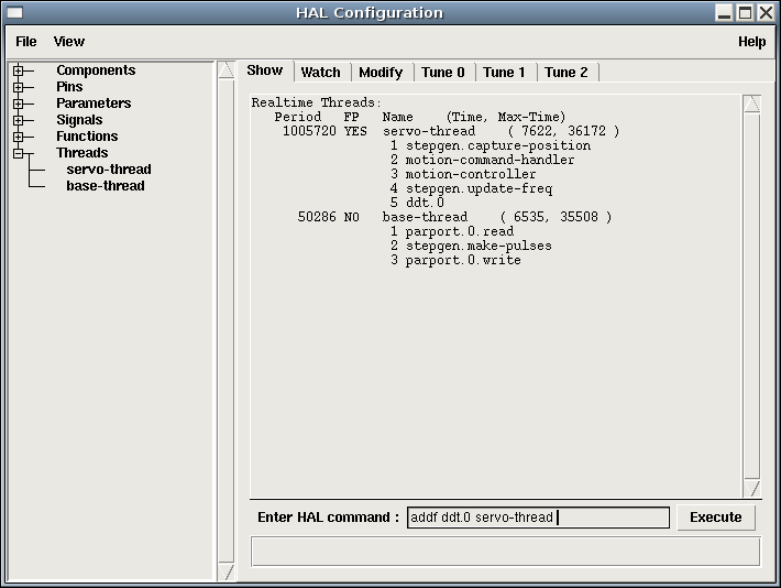
Next we need to connect this block to something. But how do we know what pins are available? The answer is to look under pins. There we find ddt and see this:
Component Pins: +
Owner Type Dir Value Name +
08 float R- 0.00000e+00 ddt.0.in +
08 float -W 0.00000e+00 ddt.0.out
That looks easy enough to understand, but what signal or pin do we want to connect to it? It could be an axis pin, a stepgen pin, or a signal. We see this when we look at axis.0:
Component Pins: +
Owner Type Dir Value Name +
03 float -W 0.00000e+00 axis.0.motor-pos-cmd ==> Xpos-cmd
So it looks like Xpos-cmd should be a good signal to use. Back to the editor where we enter the following command:
linksp Xpos-cmd ddt.0.in
Now if we look at the Xpos-cmd signal using the tree node we’ll see what we’ve done:
Signals: +
Type Value Name +
float 0.00000e+00 Xpos-cmd +
<== axis.0.motor-pos-cmd +
==> ddt.0.in +
==> stepgen.0.position-cmd
We see that this signal comes from axis.o.motor-pos-cmd and goes to both ddt.0.in and stepgen.0.position-cmd. By connecting our block to the signal we have avoided any complications with the normal flow of this motion command.
The Hal Show Area uses halcmd to discover what is happening in a running HAL. It gives you complete information about what it has discovered. It also updates as you issue commands from the little editor panel to modify that HAL. There are times when you want a different set of things displayed without all of the information available in this area. That is where the Hal Watch Area is of value.
1.7.4. Hal Watch Area
Clicking the watch tab produces a blank canvas. You can add signals
and pins to this canvas and watch their values.
[The refresh
rate of the watch display is much lower than Halmeter or
Halscope. If you need good resolution of the timing of signals those
tools are much more effective.
]
You can add signals or pins when the watch tab is displayed by
clicking on the name of it. Figure [cap:Watch-Display] shows this
canvas with several "bit" type signals. These signals include
enable-out for the first three axes and two of the three iocontrol
"estop" signals. Notice that the axes are not enabled even though the
estop signals say that EMC is not in estop. A quick look at TkEMC shows
that the condition of EMC is ESTOP RESET. The amp enables do not turn
true until the machine has been turned on.
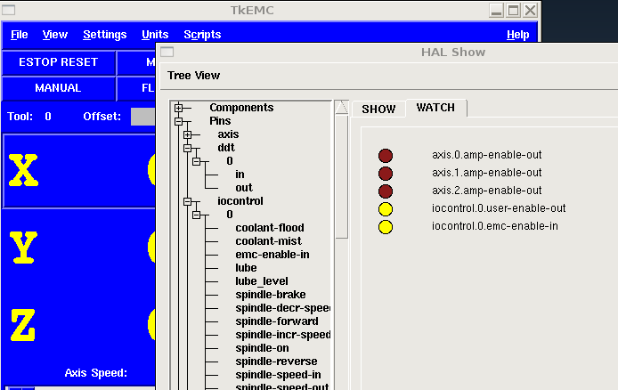
Watch displays bit type (binary) values using colored circles representing LEDs. They show as dark brown when a bit signal or pin is false, and as light yellow whenever that signal is true. If you select a pin or signal that is not a bit type (binary) signal, watch will show it as a numerical value.
Watch will quickly allow you to test switches or see the effect of changes that you make to EMC while using the graphical interface. Watch’s refresh rate is a bit slow to see stepper pulses, but you can use it for these if you move an axis very slowly or in very small increments of distance. If you’ve used IO_Show in EMC, the watch page in halshow can be set up to watch a parport much as IO_Show did.
2. Basic Configuration
2.1. Introduction
The preferred way to set up a standard stepper machine is with the Step Configuration Wizard. See the Getting Started Guide.
This chapter describes some of the more common settings for manually setting up a stepper based system. Because of the various possibilities of configuring EMC2, it is very hard to document them all, and keep this document relatively short.
The most common EMC2 usage is for stepper based systems. These systems are using stepper motors with drives that accept step & direction signals.
It is one of the simpler setups, because the motors run open-loop (no feedback comes back from the motors), yet the system needs to be configured properly so the motors don’t stall or lose steps.
Most of this chapter is based on the sample config released along with EMC2. The config is called stepper, and usually it is found in /etc/emc2/sample-configs/stepper.
2.2. Maximum step rate
With software step generation, the maximum step rate is one step per two BASE_PERIODs for step-and-direction output. The maximum requested step rate is the product of an axis' MAX_VELOCITY and its INPUT_SCALE. If the requested step rate is not attainable, following errors will occur, particularly during fast jogs and G0 moves.
If your stepper driver can accept quadrature input, use this mode. With a quadrature signal, one step is possible for each BASE_PERIOD, doubling the maximum step rate.
The other remedies are to decrease one or more of: the BASE_PERIOD (setting this too low will cause the machine to become unresponsive or even lock up), the INPUT_SCALE (if you can select different step sizes on your stepper driver, change pulley ratios, or leadscrew pitch), or the MAX_VELOCITY and STEPGEN_MAXVEL.
If no valid combination of BASE_PERIOD, INPUT_SCALE, and MAX_VELOCITY is acceptable, then consider using hardware step generation (such as with the emc2-supported Universal Stepper Controller, Mesa cards, and others.)
2.3. Pinout
One of the major flaws in EMC was that you couldn’t specify the pinout without recompiling the source code. EMC2 is far more flexible, and now (thanks to the Hardware Abstraction Layer) you can easily specify which signal goes where. See the HAL manual for more detailed information on HAL.
As it is described in the HAL Introduction and tutorial, we have signals, pins and parameters inside the HAL.
The ones relevant for our pinout are
[Note: we are only
presenting one axis to keep it short, all others are
similar.
]
:
signals: Xstep, Xdir & Xen
Depending on what you have chosen in your .ini file you are using either standard_pinout.hal or xylotex_pinout.hal. These are two files that instruct the HAL how to link the various signals & pins. Further on we’ll investigate the standard_pinout.hal.
2.3.1. standard_pinout.hal
This file contains several HAL commands, and usually looks like this:
# standard pinout config file for 3-axis steppers
# using a parport for I/O
#
# first load the parport driver
loadrt hal_parport cfg="0x0378"
#
# next connect the parport functions to threads
# read inputs first
addf parport.0.read base-thread 1
# write outputs last
addf parport.0.write base-thread -1
#
# finally connect physical pins to the signals
net Xstep => parport.0.pin-03-out
net Xdir  => parport.0.pin-02-out
net Ystep => parport.0.pin-05-out
net Ydir  => parport.0.pin-04-out
net Zstep => parport.0.pin-07-out
net Zdir  => parport.0.pin-06-out

# create a signal for the estop loopback
net estop-loop iocontrol.0.user-enable-out iocontrol.0.emc-enable-in

# create signals for tool loading loopback
net tool-prep-loop iocontrol.0.tool-prepare iocontrol.0.tool-prepared
net tool-change-loop iocontrol.0.tool-change iocontrol.0.tool-changed

# connect "spindle on" motion controller pin to a physical pin
net spindle-on motion.spindle-on => parport.0.pin-09-out

###
### You might use something like this to enable chopper drives when machine ON
### the Xen signal is defined in core_stepper.hal
###

# net Xen => parport.0.pin-01-out

###
### If you want active low for this pin, invert it like this:
###

# setp parport.0.pin-01-out-invert 1

###
### A sample home switch on the X axis (axis 0).  make a signal,
### link the incoming parport pin to the signal, then link the signal
### to EMC's axis 0 home switch input pin
###

# net Xhome parport.0.pin-10-in => axis.0.home-sw-in

###
### Shared home switches all on one parallel port pin?
### that's ok, hook the same signal to all the axes, but be sure to
### set HOME_IS_SHARED and HOME_SEQUENCE in the ini file.  See the
### user manual!
###

# net homeswitches <= parport.0.pin-10-in
# net homeswitches => axis.0.home-sw-in
# net homeswitches => axis.1.home-sw-in
# net homeswitches => axis.2.home-sw-in

###
### Sample separate limit switches on the X axis (axis 0)
###

# net X-neg-limit parport.0.pin-11-in => axis.0.neg-lim-sw-in
# net X-pos-limit parport.0.pin-12-in => axis.0.pos-lim-sw-in

###
### Just like the shared home switches example, you can wire together
### limit switches.  Beware if you hit one, EMC will stop but can't tell
### you which switch/axis has faulted.  Use caution when recovering from this.
###

# net Xlimits parport.0.pin-13-in => axis.0.neg-lim-sw-in axis.0.pos-lim-sw-in
The files starting with # are comments, and their only purpose is to guide the reader through the file.
2.3.2. Overview of the standard_pinout.hal
There are a couple of operations that get executed when the standard_pinout.hal gets executed / interpreted:
-
The Parport driver gets loaded (see [sec:Parport] for details)
-
The read & write functions of the parport driver get assigned to the base thread
[the fastest thread in the EMC2 setup, usually the code gets executed every few microseconds ]
-
The step & direction signals for axes X,Y,Z get linked to pins on the parport
-
Further IO signals get connected (estop loopback, toolchanger loopback)
-
A spindle-on signal gets defined and linked to a parport pin
2.3.3. Changing the standard_pinout.hal
If you want to change the standard_pinout.hal file, all you need is a text editor. Open the file and locate the parts you want to change.
If you want for example to change the pin for the X-axis Step & Directions signals, all you need to do is to change the number in the parport.0.pin-XX-out name:
net Xstep parport.0.pin-03-out
can be changed to:
net Xstep parport.0.pin-02-out
or basically any other numbers you like.
Hint: make sure you don’t have more than one signal connected to the same pin.
2.3.4. Changing the polarity of a signal
If external hardware expects an “active low” signal, set the corresponding -invert parameter. For instance, to invert the spindle control signal:
setp parport.0.pin-09-invert TRUE
2.3.5. Adding PWM Spindle Speed Control
If your spindle can be controlled by a PWM signal, use the pwmgen component to create the signal:
loadrt pwmgen output_type=0
This assumes that the spindle controller’s response to PWM is simple: 0% PWM gives 0 RPM, 10% PWM gives 180 RPM, etc. If there is a minimum PWM required to get the spindle to turn, follow the example in the nist-lathe sample configuration to use a scale component.
2.3.6. Adding an enable signal
Some amplifiers (drives) require an enable signal before they accept and command movement of the motors. For this reason there are already defined signals called Xen, Yen, Zen.
To connect them use the following example:
net Xen parport.0.pin-08-out
You can either have one single pin that enables all drives; or several, depending on the setup you have. Note, however, that usually when one axis faults, all the other drives will be disabled as well, so having only one enable signal / pin for all drives is a common practice.
2.3.7. Adding an external ESTOP button
As you can see in [sub:standard_pinout.hal] by default the stepper
configuration assumes no external ESTOP button.
[An extensive
explanation of hooking up ESTOP circuitry is explained in
the wiki.linuxcnc.org and in the Integrator Manual
]
To add a simple external button you need to replace the line:
net estop-loop iocontrol.0.user-enable-out iocontrol.0.emc-enable-in
with
net estop-loop parport.0.pin-01-in iocontrol.0.emc-enable-in
This assumes an ESTOP switch connected to pin 01 on the parport. As
long as the switch will stay pushed
[make sure you use a
maintained switch for ESTOP.
]
, EMC2 will be in the ESTOP state. When the external button gets
released EMC2 will imediately switch to the ESTOP-RESET state, and all
you need to do is switch to Machine On and you’ll be
able to continue your work with EMC2.
3. HAL Components
3.1. Commands and Userspace Components
Some of these will have expanded descriptions from the man pages. Some will have limited descriptions. All of the components have man pages. From this list you know what components exist and can use man n name to get additional information. For example in a terminal window type
man 1 axis
to view the information in the man page.
-
= AXIS Remote Interface
-
= AXIS EMC (The Enhanced Machine Controller) Graphical User Interface
-
= A program for loading a Xilinx Bitfile program into the FPGA of an Anything I/O board from Mesa
-
= Build, compile and install EMC HAL components
-
= EMC (The Enhanced Machine Controller)
-
= control HAL pins with any Linux input device, including USB HID devices
-
= manipulate the Enhanced Machine Controller HAL from the command line
-
= observe HAL pins, signals, and parameters
-
= manipulate the Enhanced Machine Controller HAL from the command line
-
= sample data from HAL in realtime
-
= stream file data into HAL in real time
-
= observe HAL pins and command EMC through NML
-
= accepts NML I/O commands, interacts with HAL in userspace
-
= accepts NML I/O commands, interacts with HAL in userspace
-
= Virtual Control Panel for EMC2
3.2. Realtime Components
Some of these will have expanded descriptions from the man pages. Some will have limited descriptions. All of the components have man pages. From this list you know what components exist and can use man n name to get additional information in a terminal window.
3.2.1. abs
Compute the absolute value and sign of the input signal
loadrt abs [count=N|names=name1[,name2...]]
addf abs.N|name thread-name
abs.N.in (float in) Input value
abs.N.out (float out) Output Value, always positive
abs.N.sign (bit out) Sign of Input, false = positive, true = negative
The first abs loaded will be abs.0 and each one after that the "N" number will increment.
3.2.2. and2
Two-input AND gate. For out to be true both inputs must be true
loadrt and2 [count=N|names=name1[,name2...]]
addf and2.N|name thread-name
and2.N.in0 (bit in) Input 0
and2.N.in1 (bit in) Input 1
and2.N.out (bit out) Output
3.2.3. at_pid
proportional/integral/derivative controller with auto tuning
3.2.4. axis
accepts NML motion commands, interacts with HAL in realtime
3.2.5. biquad
Biquad IIR filter
3.2.6. bldc_hall3
3-wire Bipolar trapezoidal commutation BLDC motor driver using Hall sensors
3.2.7. blend
Perform linear interpolation between two values
loadrt blend [count=N|names=name1[,name2...]]
addf blend.N|name thread-name
blend.N.in1 (float in) First input.
blend.N.in2 (float in) Second input.
blend.N.select (float in) Select input.
blend.N.out (float out) Output value.
blend.N.open (bit r/w)
If select is equal to 0.0 output is equal to in1.
If select is equal to 1.0, the output is equal to in2.
For select values between 0.0 and 1.0, the output changes linearly from in1 to in2.
If blend.N.open is true, select values outside the range 0.0 to 1.0 give values outside the range in1 to in2. If false, outputs are clamped to the the range in1 to in2
3.2.8. charge_pump
Create a square-wave for the "charge pump" input of some controller boards
loadrt charge_pump
addf charge-pump
charge-pump.out (bit out)
charge-pump.enable (bit in) default = TRUE
Outputs a square wave if enable is TRUE or unconnected, low if enable is FALSE
3.2.9. clarke2
Two input version of Clarke transform
loadrt clarke2 [count=N|names=name1[,name2...]]
addf clarke2.N | name
clarke2.N.a (float in) phase a input
clarke2.N.b (float in) phase b input
clarke2.N.x (float out) cartesian components of output
clarke2.N.y (float out) cartesian components of output
The Clarke transform can be used to translate a vector quantity from a three phase system (three components 120 degrees apart) to a two phase Cartesian system.
clarke2 implements a special case of the Clarke transform, which only needs two of the three input phases. In a three wire three phase system, the sum of the three phase currents or voltages must always be zero. As a result only two of the three are needed to completely define the current or voltage. clarke2 assumes that the sum is zero, so it only uses phases A and B of the input. Since the H (homopolar) output will always be zero in this case, it is not generated.
3.2.10. clarke3
Clarke (3 phase to cartesian) transform
loadrt clarke3 [count=N|names=name1[,name2...]]
addf clarke3.N | name
clarke3.N.a (float in) three phase input vector
clarke3.N.b (float in) three phase input vector
clarke3.N.c (float in) three phase input vector
clarke3.N.x (float out) cartesian components of output
clarke3.N.y (float out) cartesian components of output
clarke3.N.h (float out) homopolar component of output
The Clarke transform can be used to translate a vector quantity from a three phase system (three components 120 degrees apart) to a two phase Cartesian system (plus a homopolar component if the three phases don’t sum to zero).
clarke3 implements the general case of the transform, using all three phases. If the three phases are known to sum to zero, see clarke2 for a simpler version.
3.2.11. clarkeinv
Inverse Clarke transform
loadrt clarkeinv [count=N|names=name1[,name2...]]
addf clarkeinv.N | name
clarkeinv.N.x (float in) cartesian components of input
clarkeinv.N.y (float in) cartesian components of input
clarkeinv.N.h (float in) homopolar component of input (usually zero)
clarkeinv.N.a (float out) three phase output vector
clarkeinv.N.b (float out) three phase output vector
clarkeinv.N.c (float out) three phase output vector
.
The inverse Clarke transform can be used to translate a vector quantity from Cartesian coordinate system to a three phase system (three components 120 degrees apart).
3.2.12. classicladder
Realtime software plc based on ladder logic
3.2.13. comp
Two input comparator with hysteresis
3.2.14. constant
Use a parameter to set the value of a pin
3.2.15. conv_bit_s32
Convert a value from bit to s32
3.2.16. conv_bit_u32
Convert a value from bit to u32
3.2.17. conv_float_s32
Convert a value from float to s32
3.2.18. conv_float_u32
Convert a value from float to u32
3.2.19. conv_s32_bit
Convert a value from s32 to bit
3.2.20. conv_s32_float
Convert a value from u32 to bit
3.2.21. conv_s32_u32
Convert a value from s32 to u32
3.2.22. conv_u32_bit
Convert a value from u32 to bit
3.2.23. conv_u32_float
Convert a value from u32 to float
3.2.24. conv_u32_s32
Convert a value from u32 to s32
3.2.25. counter
counts input pulses (deprecated)
3.2.26. ddt
Compute the derivative of the input function
3.2.27. deadzone
Return the center if within the threshold
3.2.28. debounce
filter noisy digital inputs, for more information see [sec:Debounce]
3.2.29. edge
Edge detector
3.2.30. encoder
software counting of quadrature encoder signals, for more information see [sec:Encoder]
3.2.31. encoder_ratio
an electronic gear to synchronize two axes
3.2.32. estop_latch
ESTOP latch
3.2.33. feedcomp
Multiply the input by the ratio of current velocity to the feed rate
3.2.34. flipflop
D type flip-flop
3.2.35. freqgen
software step pulse generation
3.2.36. gantrykins
A kinematics module that maps one axis to multiple joints
3.2.37. gearchange
Select from one two speed ranges
3.2.38. genhexkins
Gives six degrees of freedom in position and orientation (XYZABC). The location of the motors is defined at compile time.
3.2.39. genserkins
Kinematics that can model a general serial-link manipulator with up to 6 angular joints.
3.2.40. hm2_7i43
HAL driver for the Mesa Electronics 7i43 EPP Anything IO board with HostMot2
3.2.41. hm2_pci
HAL driver for the Mesa Electronics 5i20, 5i22, 5i23, 4i65, and 4i68 Anything IO boards, with HostMot2 firmware
3.2.42. hostmot2
HAL driver for the Mesa Electronics HostMot2 firmware
3.2.43. hypot
Three-input hypotenuse (Euclidean distance) calculator
3.2.44. ilowpass
Low-pass filter with integer inputs and outputs
3.2.45. integ
Integrator
3.2.46. invert
Compute the inverse of the input signal
3.2.47. joyhandle
sets nonlinear joypad movements, deadbands and scales
3.2.48. kins
kinematics definitions for emc2
3.2.49. knob2float
Convert counts (probably from an encoder) to a float value
3.2.50. limit1
Limit the output signal to fall between min and max
3.2.51. limit2
Limit the output signal to fall between min and max
3.2.52. limit3
Limit the output signal to fall between min and max
3.2.53. logic
Experimental general logic function component
3.2.54. lowpass
Low-pass filter
3.2.55. lut5
Arbitrary 5-input logic function based on a look-up table
3.2.56. maj3
Compute the majority of 3 inputs
3.2.57. match8
8-bit binary match detector
3.2.58. maxkins
Kinematics for a tabletop 5 axis mill named "max" with tilting head (B axis) and horizintal rotary mounted to the table (C axis). Provides UVW motion in the rotated coordinate system. The source file, maxkins.c, may be a useful starting point for other 5-axis systems.
3.2.59. minmax
Track the minimum and maximum values of the input to the outputs
3.2.60. motion
accepts NML motion commands, interacts with HAL in realtime
3.2.61. mult2
Product of two inputs
3.2.62. mux2
Select from one of two input values
3.2.63. mux4
Select from one of four input values
3.2.64. mux8
Select from one of eight input values
3.2.65. near
Determine whether two values are roughly equal
3.2.66. not
Inverter
3.2.67. offset
Adds an offset to an input, and subtracts it from the feedback value
3.2.68. oneshot
one-shot pulse generator
3.2.69. or2
Two-input OR gate
3.2.70. pid
proportional/integral/derivative controller, for more information see [sec:PID]
3.2.71. pluto_servo
Hardware driver and firmware for the Pluto-P parallel-port FPGA, for use with servos
3.2.72. pluto_step
Hardware driver and firmware for the Pluto-P parallel-port FPGA, for use with steppers
3.2.73. pwmgen
software PWM/PDM generation, for more information see [sec:PWMgen]
3.2.74. rotatekins
The X and Y axes are rotated 45 degrees compared to the joints 0 and 1.
3.2.75. sample_hold
Sample and Hold
3.2.76. sampler
sample data from HAL in real time
3.2.77. scale
applies a scale and offset to its input
3.2.78. scarakins
kinematics for SCARA-type robots
3.2.79. select8
8-bit binary match detector
3.2.80. serport
Hardware driver for the digital I/O bits of the 8250 and 16550 serial port
3.2.81. siggen
signal generator, for more information see [sec:Siggen]
3.2.82. sim_encoder
simulated quadrature encoder, for more information see [sec:Simulated-Encoder]
3.2.83. sphereprobe
Probe a pretend hemisphere
3.2.84. stepgen
software step pulse generation, for more information see [sec:Stepgen]
3.2.85. steptest
Used by Stepconf to allow testing of acceleration and velocity values for an axis
3.2.86. streamer
stream file data into HAL in real time
3.2.87. sum2
Sum of two inputs (each with a gain) and an offset
3.2.88. supply
set output pins with values from parameters (deprecated)
3.2.89. thc
Torch Height Control using a Mesa THC card.
3.2.90. threads
creates hard realtime HAL threads
3.2.91. threadtest
component for testing thread behavior
3.2.92. timedelay
The equivalent of a time-delay relay
3.2.93. timedelta
component that measures thread scheduling timing behavior
3.2.94. toggle
push-on, push-off from momentary pushbuttons
3.2.95. toggle2nist
toggle button to nist logic
3.2.96. tripodkins
The joints represent the distance of the controlled point from three predefined locations (the motors), giving three degrees of freedom in position (XYZ)
3.2.97. tristate_bit
Place a signal on an I/O pin only when enabled, similar to a tristate buffer in electronics
3.2.98. tristate_float
Place a signal on an I/O pin only when enabled, similar to a tristate buffer in electronics
3.2.99. trivkins
There is a 1:1 correspondence between joints and axes. Most standard milling machines and lathes use the trivial kinematics module.
3.2.100. updown
Counts up or down, with optional limits and wraparound behavior
3.2.101. wcomp
Window comparator
3.2.102. weighted_sum
convert a group of bits to an integer
3.2.103. xor2
Two-input XOR (exclusive OR) gate
.
.
.
.
.
3.3. Hal Meter
Hal Meter can be loaded from a terminal or from Axis. Hal Meter is faster than Hal Show displaying values. Hal Meter has two windows, one to pick the pin, signal, or parameter to monitor and one that displays the value. Multiple Hal Meters can be open at the same time. If you use a script to open multiple Hal Meters you can set the position of each one with -g X Y relative to the upper left corner of your screen. See the man page for more options.
loadusr halmeter pin hm2.0.stepgen.00.velocity-fb -g 0 500
![]image::images/hal-meter02.png[](hal/images/hal-meter01.png)
3.4. Stepgen
This component provides software based generation of step pulses in response to position or velocity commands. In position mode, it has a built in pre-tuned position loop, so PID tuning is not required. In velocity mode, it drives a motor at the commanded speed, while obeying velocity and acceleration limits. It is a realtime component only, and depending on CPU speed, etc, is capable of maximum step rates of 10kHz to perhaps 50kHz. Figure [fig:Stepgen-Block-Diag] shows three block diagrams, each is a single step pulse generator. The first diagram is for step type 0, (step and direction). The second is for step type 1 (up/down, or pseudo-PWM), and the third is for step types 2 through 14 (various stepping patterns). The first two diagrams show position mode control, and the third one shows velocity mode. Control mode and step type are set independently, and any combination can be selected.
3.4.1. Installing
 emc2$ *halcmd loadrt stepgen step_type=<type-array>
[ctrl_type=<ctrl_array>]*
<type-array> is a series of comma separated decimal integers. Each number causes a single step pulse generator to be loaded, the value of the number determines the stepping type. <ctrl_array> is a comma separated series of “p`” or “`v`” characters, to specify position or velocity mode. `ctrl_type is optional, if ommitted, all of the step generators will be position mode. For example:
emc2# *halcmd loadrt stepgen step_type=0,0,2 ctrl_type=p,p,v*
will install three step generators. The first two use step type 0 (step and direction) and run in position mode. The last one uses step type 2 (quadrature) and runs in velocity mode. The default value for <config-array> is “0,0,0” which will install three type 0 (step/dir) generators. The maximum number of step generators is 8 (as defined by MAX_CHAN in stepgen.c). Each generator is independent, but all are updated by the same function(s) at the same time. In the following descriptions, <chan> is the number of a specific generator. The first generator is number 0.
3.4.2. Removing
emc2$ *halcmd unloadrt stepgen*
3.4.3. Pins
Each step pulse generator will have only some of these pins, depending on the step type and control type selected.
-
(float)` stepgen.<chan>.position-cmd` — Desired motor position, in position units (position mode only).
-
(float)` stepgen.<chan>.velocity-cmd` — Desired motor velocity, in position units per second (velocity mode only).
-
(s32) ``stepgen.<chan>.counts — Feedback position in counts, updated by capture_position().
-
(float) ``stepgen.<chan>.position-fb — Feedback position in position units, updated by capture_position().
-
(bit)` stepgen.<chan>.enable` — Enables output steps - when false, no steps are generated.
-
(bit)` stepgen.<chan>.step` — Step pulse output (step type 0 only).
-
(bit)` stepgen.<chan>.dir` — Direction output (step type 0 only).
-
(bit) ``stepgen.<chan>.up — UP pseudo-PWM output (step type 1 only).
-
(bit) ``stepgen.<chan>.down — DOWN pseudo-PWM output (step type 1 only).
-
(bit) ``stepgen.<chan>.phase-A — Phase A output (step types 2-14 only).
-
(bit) ``stepgen.<chan>.phase-B — Phase B output (step types 2-14 only).
-
(bit) ``stepgen.<chan>.phase-C — Phase C output (step types 3-14 only).
-
(bit) ``stepgen.<chan>.phase-D — Phase D output (step types 5-14 only).
-
(bit) ``stepgen.<chan>.phase-E — Phase E output (step types 11-14 only).
3.4.4. Parameters
-
(float)` stepgen.<chan>.position-scale` — Steps per position unit. This parameter is used for both output and feedback.
-
(float)` stepgen.<chan>.maxvel` — Maximum velocity, in position units per second. If 0.0, has no effect.
-
(float)` stepgen.<chan>.maxaccel` — Maximum accel/decel rate, in positions units per second squared. If 0.0, has no effect.
-
(float)` stepgen.<chan>.frequency` — The current step rate, in steps per second.
-
(float)` stepgen.<chan>.steplen` — Length of a step pulse (step type 0 and 1) or minimum time in a given state (step types 2-14), in nano-seconds.
-
(float)` stepgen.<chan>.stepspace` — Minimum spacing between two step pulses (step types 0 and 1 only), in nano-seconds.
-
(float)` stepgen.<chan>.dirsetup` — Minimum time from a direction change to the beginning of the next step pulse (step type 0 only), in nanoseconds.
-
(float)` stepgen.<chan>.dirhold` — Minmum time from the end of a step pulse to a direction change (step type 0 only), in nanoseconds.
-
(float)` stepgen.<chan>.dirdelay` — Minmum time any step to a step in the opposite direction (step types 1-14 only), in nano-seconds.
-
(s32)` stepgen.<chan>.rawcounts` — The raw feedback count, updated by make_pulses().
In position mode, the values of maxvel and maxaccel are used by the internal position loop to avoid generating step pulse trains that the motor cannot follow. When set to values that are appropriate for the motor, even a large instantaneous change in commanded position will result in a smooth trapezoidal move to the new location. The algorithm works by measuring both position error and velocity error, and calculating an acceleration that attempts to reduce both to zero at the same time. For more details, including the contents of the “control equation” box, consult the code.
In velocity mode, maxvel is a simple limit that is applied to the commanded velocity, and maxaccel is used to ramp the actual frequency if the commanded velocity changes abruptly. As in position mode, proper values for these parameters ensure that the motor can follow the generated pulse train.
3.4.5. Step Types
The step generator supports 15 different “step types”. Step type 0 is the most familiar, standard step and direction. When configured for step type 0, there are four extra parameters that determine the exact timing of the step and direction signals. See figure [fig:StepDir-timing] for the meaning of these parameters. The parameters are in nanoseconds, but will be rounded up to an integer multiple of the thread period for the threaed that calls make_pulses(). For example, if make_pulses() is called every 16uS, and steplen is 20000, then the step pulses will be 2 x 16 = 32uS long. The default value for all four of the parameters is 1nS, but the automatic rounding takes effect the first time the code runs. Since one step requires steplen nS high and stepspace nS low, the maximum frequency is 1,000,000,000 divided by (steplen+stepspace). If maxfreq is set higher than that limit, it will be lowered automatically. If maxfreq is zero, it will remain zero, but the output frequency will still be limited.
Step type 1 has two outputs, up and down. Pulses appear on one or the other, depending on the direction of travel. Each pulse is steplen nS long, and the pulses are separated by at least stepspace nS. The maximum frequency is the same as for step type 0. If maxfreq is set higher than the limit it will be lowered. If maxfreq is zero, it will remain zero but the output frequency will still be limited.
Step types 2 through 14 are state based, and have from two to five outputs. On each step, a state counter is incremented or decremented. Figures [fig:Quad-Three-Phase], [fig:Four-Phase], and [fig:Five-Phase] show the output patterns as a function of the state counter. The maximum frequency is 1,000,000,000 divided by steplen, and as in the other modes, maxfreq will be lowered if it is above the limit.
3.4.6. Functions
The component exports three functions. Each function acts on all of the step pulse generators - running different generators in different threads is not supported.
-
(funct)` stepgen.make-pulses` — High speed function to generate and count pulses (no floating point).
-
(funct)` stepgen.update-freq` — Low speed function does position to velocity conversion, scaling and limiting.
-
(funct)` stepgen.capture-position` — Low speed function for feedback, updates latches and scales position.
The high speed function stepgen.make-pulses should be run in a very fast thread, from 10 to 50uS depending on the capabilities of the computer. That thread’s period determines the maximum step frequency, since steplen, stepspace, dirsetup, dirhold, and dirdelay are all rounded up to a integer multiple of the thread periond in nanoseconds. The other two functions can be called at a much lower rate.
3.5. PWMgen
This component provides software based generation of PWM (Pulse Width Modulation) and PDM (Pulse Density Modulation) waveforms. It is a realtime component only, and depending on CPU speed, etc, is capable of PWM frequencies from a few hundred Hertz at pretty good resolution, to perhaps 10KHz with limited resolution.
3.5.1. Installing
emc2$
<config-array> is a series of comma separated decimal integers. Each number causes a single PWM generator to be loaded, the value of the number determines the output type. For example:
emc2$
will install three PWM generators. The first one will use output type 0 (PWM only), the next uses output type 1 (PWM and direction) and the last one uses output type 2 (UP and DOWN). There is no default value, if <config-array> is not specified, no PWM generators will be installed. The maximum number of frequency generators is 8 (as defined by MAX_CHAN in pwmgen.c). Each generator is independent, but all are updated by the same function(s) at the same time. In the following descriptions, <chan> is the number of a specific generator. The first generator is number 0.
3.5.2. Removing
emc2$
3.5.3. Pins
Each PWM generator will have the following pins:
-
(float)` pwmgen.<chan>.value` — Command value, in arbitrary units. Will be scaled by the scale parameter (see below).
-
(bit)` pwmgen.<chan>.enable` — Enables or disables the PWM generator outputs.
Each PWM generator will also have some of these pins, depending on the output type selected:
-
(bit)` pwmgen.<chan>.pwm` — PWM (or PDM) output, (output types 0 and 1 only).
-
(bit)` pwmgen.<chan>.dir` — Direction output (output type 1 only).
-
(bit) ``pwmgen.<chan>.up — PWM/PDM output for positive input value (output type 2 only).
-
(bit) ``pwmgen.<chan>.down — PWM/PDM output for negative input value (output type 2 only).
3.5.4. Parameters
-
(float)` pwmgen.<chan>.scale` — Scaling factor to convert value from arbitrary units to duty cycle.
-
(float)` pwmgen.<chan>.pwm-freq` — Desired PWM frequency, in Hz. If 0.0, generates PDM instead of PWM. If set higher than internal limits, next call of update_freq() will set it to the internal limit. If non-zero, and dither is false, next call of update_freq() will set it to the nearest integer multiple of the make_pulses() function period.
-
(bit)` pwmgen.<chan>.dither-pwm` — If true, enables dithering to achieve average PWM frequencies or duty cycles that are unobtainable with pure PWM. If false, both the PWM frequency and the duty cycle will be rounded to values that can be achieved exactly.
-
(float)` pwmgen.<chan>.min-dc` — Minimum duty cycle, between 0.0 and 1.0 (duty cycle will go to zero when disabled, regardless of this setting).
-
(float)` pwmgen.<chan>.max-dc` — Maximum duty cycle, between 0.0 and 1.0.
-
(float)` pwmgen.<chan>.curr-dc` — Current duty cycle - after all limiting and rounding (read only).
3.5.5. Output Types
The PWM generator supports three different “output types”. Type 0 has a single output pin. Only positive commands are accepted, negative values are treated as zero (and will be affected by min-dc if it is non-zero). Type 1 has two output pins, one for the PWM/PDM signal and one to indicate direction. The duty cycle on the PWM pin is based on the absolute value of the command, so negative values are acceptable. The direction pin is false for positive commands, and true for negative commands. Finally, type 2 also has two outputs, called up and down. For positive commands, the PWM signal appears on the up output, and the down output remains false. For negative commands, the PWM signal appears on the down output, and the up output remains false. Output type 2 is suitable for driving most H-bridges.
3.5.6. Functions
The component exports two functions. Each function acts on all of the PWM generators - running different generators in different threads is not supported.
-
(funct)` pwmgen.make-pulses` — High speed function to generate PWM waveforms (no floating point).
-
(funct)` pwmgen.update` — Low speed function to scale and limit value and handle other paremeters.
The high speed function pwmgen.make-pulses should be run in a very fast thread, from 10 to 50uS depending on the capabilities of the computer. That thread’s period determines the maximum PWM carrier frequency, as well as the resolution of the PWM or PDM signals. The other function can be called at a much lower rate.
3.6. Encoder
This component provides software based counting of signals from quadrature encoders. It is a realtime component only, and depending on CPU speed, latency, etc, is capable of maximum count rates of 10kHz to perhaps up to 50kHz. Figure [fig:Encoder-Block-Diag] is a block diagram of one channel of encoder counter.
3.6.1. Installing
<counters> is the number of encoder counters that you want to install. If numchan is not specified, three counters will be installed. The maximum number of counters is 8 (as defined by MAX_CHAN in encoder.c). Each counter is independent, but all are updated by the same function(s) at the same time. In the following descriptions, <chan> is the number of a specific counter. The first counter is number 0.
3.6.2. Removing
emc2$
3.6.3. Pins
-
encoder.<chan>.counter-mode (bit, I/O) (default: FALSE) — Enables counter mode. When true, the counter counts each rising edge of the phase-A input, ignoring the value on phase-B. This is useful for counting the output of a single channel (non-quadrature) sensor. When false, it counts in quadrature mode.
-
encoder.<chan>.counts (s32, Out) — Position in encoder counts.
-
encoder.<chan>.counts-latched (s32, Out) — Not used at this time.
-
encoder.<chan>.index-enable (bit, I/O) — When True, counts and position are reset to zero on next rising edge of Phase Z. At the same time, index-enable is reset to zero to indicate that the rising edge has occoured. The index-enable pin is bi-directional. If index-enable is False, the Phase Z channel of the encoder will be ignored, and the counter will count normally. The encoder driver will never set index-enable True. However, some other component may do so.
-
encoder.<chan>.latch-falling (bit, In) (default: TRUE) — Not used at this time.
-
encoder.<chan>.latch-input (bit, In) (default: TRUE) — Not used at this time.
-
encoder.<chan>.latch-rising (bit, In) — Not used at this time.
-
encoder.<chan>.min-speed-estimate (float, in) — Determine the minimum true velocity magnitude at which velocity will be estimated as nonzero and postition-interpolated will be interpolated. The units of min-speed-estimate are the same as the units of velocity . Scale factor, in counts per length unit. Setting this parameter too low will cause it to take a long time for velocity to go to 0 after encoder pulses have stopped arriving.
-
encoder.<chan>.phase-A (bit, In) — Phase A of the quadrature encoder signal.
-
encoder.<chan>.phase-B (bit, In) — Phase B of the quadrature encoder signal.
-
encoder.<chan>.phase-Z (bit, In) — Phase Z (index pulse) of the quadrature encoder signal.
-
encoder.<chan>.position (float, Out) — Position in scaled units (see position-scale).
-
encoder.<chan>.position-interpolated (float, Out) — Position in scaled units, interpolated between encoder counts. The position-interpolated attempts to interpolate between encoder counts, based on the most recently measured velocity. Only valid when velocity is approximately constant and above min-speed-estimate . Do not be used for position control, since its value is incorrect at low speeds, during direction reversals, and during speed changes. However, it allows a low ppr encoder (including a one pulse per revolution "encoder") to be used for lathe threading, and may have other uses as well.
-
encoder.<chan>.position-latched (float, Out) — Not used at this time.
-
encoder.<chan>.position-scale (float, I/O) — Scale factor, in counts per length unit. For example, if position-scale is 500, then 1000 counts of the encoder will be reported as a position of 2.0 units.
-
encoder.<chan>.rawcounts (s32, In) — The raw count, as determined by update-counters. This value is updated more frequently than counts and position. It is also unaffected by reset or the index pulse.
-
encoder.<chan>.reset (bit, In) — When True, force counts and position to zero immediately.
-
encoder.<chan>.velocity (float, Out) — Velocity in scaled units per second. encoder uses an algorithm that greatly reduces quantization noise as compared to simply differentiating the position output. When the magnitude of the true velocity is below min-velocity-estimate, the velocity output is 0.
-
encoder.<chan>.x4-mode (bit, I/O) (default: TRUE) — Enables times-4 mode. When true, the counter counts each edge of the quadrature waveform (four counts per full cycle). When false, it only counts once per full cycle. In counter-mode, this parameter is ignored. The 1x mode is usefull for some jogwheels.
3.6.4. Parameters
-
encoder.<chan>.capture-position.time (s32, RO)
-
encoder.<chan>.capture-position.tmax (s32, RW)
-
encoder.<chan>.update-counters.time (s32, RO)
-
encoder.<chan>.update-counter.tmax (s32, RW)
3.6.5. Functions
The component exports two functions. Each function acts on all of the encoder counters - running different counters in different threads is not supported.
-
(funct)` encoder.update-counters` — High speed function to count pulses (no floating point).
-
(funct)` encoder.capture-position` — Low speed function to update latches and scale position.
3.7. PID
This component provides Proportional/Integeral/Derivative control loops. It is a realtime component only. For simplicity, this discussion assumes that we are talking about position loops, however this component can be used to implement other feedback loops such as speed, torch height, temperature, etc. Figure [fig:PID-block-diag] is a block diagram of a single PID loop.
3.7.1. Installing
<loops> is the number of PID loops that you want to install. If numchan is not specified, one loop will be installed. The maximum number of loops is 16 (as defined by MAX_CHAN in pid.c). Each loop is completely independent. In the following descriptions, <loopnum> is the loop number of a specific loop. The first loop is number 0.
If debug=1 is specified, the component will export a few extra parameters that may be useful during debugging and tuning. By default, the extra parameters are not exported, to save shared memory space and avoid cluttering the parameter list.
3.7.2. Removing
emc2$
3.7.3. Pins
The three most important pins are
-
(float) ``pid.<loopnum>.command — The desired position, as commanded by another system component.
-
(float) ``pid.<loopnum>.feedback — The present position, as measured by a feedback device such as an encoder.
-
(float) ``pid.<loopnum>.output — A velocity command that attempts to move from the present position to the desired position.
For a position loop, command and feedback are in position units. For a linear axis, this could be inches, mm, meters, or whatever is relevant. Likewise, for an angular axis, it could be degrees, radians, etc. The units of the output pin represent the change needed to make the feedback match the command. As such, for a position loop Output is a velocity, in inches/sec, mm/sec, degrees/sec, etc. Time units are always seconds, and the velocity units match the position units. If command and feedback are in meters, then output is in meters per second.
Each loop has two pins which are used to monitor or control the general operation of the component.
-
(float) ``pid.<loopnum>.error — Equals .command minus .feedback.
-
(bit) ``pid.<loopnum>.enable — A bit that enables the loop. If .enable is false, all integrators are reset, and the output is forced to zero. If .enable is true, the loop operates normally.
Pins used to report saturation. Saturation occurs when the output of the PID block is at its maximum or minimum limit.
-
(bit) pid.<loopnum>.saturated — True when output is saturated.
-
(float) pid.<loopnum>.saturated_s — The time the output has been saturated.
-
(s32) pid.<loopnum>.saturated_count — The time the output has been saturated.
3.7.4. Parameters
The PID gains, limits, and other tunable features of the loop are implemented as parameters.
-
(float)` pid.<loopnum>.Pgain` — Proportional gain
-
(float)` pid.<loopnum>.Igain` — Integral gain
-
(float)` pid.<loopnum>.Dgain` — Derivative gain
-
(float)` pid.<loopnum>.bias` — Constant offset on output
-
(float)` pid.<loopnum>.FF0` — Zeroth order feedforward - output proportional to command (position).
-
(float)` pid.<loopnum>.FF1` — First order feedforward - output proportional to derivative of command (velocity).
-
(float)` pid.<loopnum>.FF2` — Second order feedforward - output proportional to 2nd derivative of command (acceleration)
[FF2 is not currently implemented, but it will be added. Consider this note a “FIXME” for the code ]
. -
(float)` pid.<loopnum>.deadband` — Amount of error that will be ignored
-
(float)` pid.<loopnum>.maxerror` — Limit on error
-
(float)` pid.<loopnum>.maxerrorI` — Limit on error integrator
-
(float)` pid.<loopnum>.maxerrorD` — Limit on error derivative
-
(float)` pid.<loopnum>.maxcmdD` — Limit on command derivative
-
(float)` pid.<loopnum>.maxcmdDD` — Limit on command 2nd derivative
-
(float)` pid.<loopnum>.maxoutput` — Limit on output value
All of the max??? limits are implemented such that if the parameter value is zero, there is no limit.
If debug=1 was specified when the component was installed, four additional parameters will be exported:
-
(float)` pid.<loopnum>.errorI` — Integral of error.
-
(float)` pid.<loopnum>.errorD` — Derivative of error.
-
(float)` pid.<loopnum>.commandD` — Derivative of the command.
-
(float)` pid.<loopnum>.commandDD` — 2nd derivative of the command.
3.7.5. Functions
The component exports one function for each PID loop. This function performs all the calculations needed for the loop. Since each loop has its own function, individual loops can be included in different threads and execute at different rates.
-
(funct)` pid.<loopnum>.do_pid_calcs` — Performs all calculations for a single PID loop.
If you want to understand the exact algorithm used to compute the output of the PID loop, refer to figure [fig:PID-block-diag], the comments at the beginning of emc2/src/hal/components/pid.c , and of course to the code itself. The loop calculations are in the C function calc_pid().
3.8. Simulated Encoder
The simulated encoder is exactly that. It produces quadrature pulses with an index pulse, at a speed controlled by a HAL pin. Mostly useful for testing.
3.8.1. Installing
emc2$ *halcmd loadrt sim-encoder num_chan=<number>*
<number> is the number of encoders that you want to simulate. If not specified, one encoder will be installed. The maximum number is 8 (as defined by MAX_CHAN in sim_encoder.c).
3.8.2. Removing
emc2$ *halcmd unloadrt sim-encoder*
3.8.3. Pins
-
(float) ``sim-encoder.<chan-num>.speed — The speed command for the simulated shaft.
-
(bit) ``sim-encoder.<chan-num>.phase-A — Quadrature output.
-
(bit) ``sim-encoder.<chan-num>.phase-B — Quadrature output.
-
(bit) ``sim-encoder.<chan-num>.phase-Z — Index pulse output.
When .speed is positive, .phase-A leads .phase-B.
3.8.4. Parameters
-
(u32)` sim-encoder.<chan-num>.ppr` — Pulses Per Revolution.
-
(float)` sim-encoder.<chan-num>.scale` — Scale Factor for speed. The default is 1.0, which means that speed is in revolutions per second. Change to 60 for RPM, to 360 for degrees per second, 6.283185 for radians per seconed, etc.
Note that pulses per revolution is not the same as counts per revolution. A pulse is a complete quadrature cycle. Most encoder counters will count four times during one complete cycle.
3.8.5. Functions
The component exports two functions. Each function affects all simulated encoders.
-
(funct)` sim-encoder.make-pulses` — High speed function to generate quadrature pulses (no floating point).
-
(funct)` sim-encoder.update-speed` — Low speed function to read speed, do scaling, and set up make-pulses.
3.9. Debounce
Debounce is a realtime component that can filter the glitches created by mechanical switch contacts. It may also be useful in other applications where short pulses are to be rejected.
3.9.1. Installing
emc2$ *halcmd loadrt debounce cfg=<config-string>*
<config-string> is a series of comma separated decimal integers. Each number installs a group of identical debounce filters, the number determines how many filters are in the group. For example:
emc2$ *halcmd loadrt debounce cfg=1,4,2*
will install three groups of filters. Group 0 contains one filter, group 1 contains four, and group 2 contains two filters. The default value for <config-string> is "1" which will install a single group containing a single filter. The maximum number of groups 8 (as defined by MAX_GROUPS in debounce.c). The maximum number of filters in a group is limited only by shared memory space. Each group is completely independent. All filters in a single group are identical, and they are all updated by the same function at the same time. In the following descriptions, <G> is the group number and <F> is the filter number within the group. The first filter is group 0, filter 0.
3.9.2. Removing
emc2$ *halcmd unloadrt debounce*
3.9.3. Pins
Each individual filter has two pins.
-
(bit) ``debounce.<G>.<F>.in — Input of filter <F> in group <G>.
-
(bit) ``debounce.<G>.<F>.out — Output of filter <F> in group <G>.
3.9.4. Parameters
Each group of filters has one parameter
[Each individual
filter also has an internal state variable. There is a
compile time switch that can export that variable as a parameter. This
is intended for testing, and simply wastes shared memory under normal
circumstances.
]
.
-
(s32) ``debounce.<G>.delay — Filter delay for all filters in group <G>.
The filter delay is in units of thread periods. The minimum delay is zero. The output of a zero delay filter exactly follows its input - it doesn’t filter anything. As delay increases, longer and longer glitches are rejected. If delay is 4, all glitches less than or equal to four thread periods will be rejected.
3.9.5. Functions
Each group of filters has one function, which updates all the filters in that group “simultaneously”. Different groups of filters can be updated from different threads at different periods.
-
(funct)` debounce.<G> — Updates all filters in group `<G>.
3.10. Siggen
Siggen is a realtime component that generates square, triangle, and sine waves. It is primarily used for testing.
3.10.1. Installing
emc2$ *halcmd loadrt siggen [num_chan=<chans>]*
<chans> is the number of signal generators that you want to install. If numchan is not specified, one signal generator will be installed. The maximum number of generators is 16 (as defined by MAX_CHAN in siggen.c). Each generator is completely independent. In the following descriptions, <chan> is the number of a specific signal generator (the numbers start at 0).
3.10.2. Removing
emc2$ *halcmd unloadrt siggen*
3.10.3. Pins
Each generator has five output pins.
-
(float) ``siggen.<chan>.sine — Sine wave output.
-
(float) ``siggen.<chan>.cosine — Cosine output.
-
(float) ``siggen.<chan>.sawtooth — Sawtooth output.
-
(float) ``siggen.<chan>.triangle — Triangle wave output.
-
(float) ``siggen.<chan>.square — Square wave output.
All five outputs have the same frequency, amplitude, and offset.
In addition to the output pins, there are three control pins:
-
(float) ``siggen.<chan>.frequency — Sets the frequency in Hertz, default value is 1 Hz.
-
(float) ``siggen.<chan>.amplitude — Sets the peak amplitude of the output waveforms, default is 1.
-
(float) ``siggen.<chan>.offset — Sets DC offset of the output waveforms, default is 0.
For example, if siggen.0.amplitude is 1.0 and siggen.0.offset is 0.0, the outputs will swing from -1.0 to +1.0. If siggen.0.amplitude is 2.5 and siggen.0.offset is 10.0, then the outputs will swing from 7.5 to 12.5.
3.10.4. Parameters
None.
[Prior to version 2.1, frequency, amplitude, and offset
were
parameters. They were changed to pins to allow control by other
components.
]
3.10.5. Functions
-
(funct)` siggen.<chan>.update` — Calculates new values for all five outputs.
4. Parallel Port
4.1. Parport
Parport is a driver for the traditional PC parallel port. The port has a total of 17 physical pins. The original parallel port divided those pins into three groups: data, control, and status. The data group consists of 8 output pins, the control group consists of 4 pins, and the status group consists of 5 input pins.
In the early 1990’s, the bidirectional parallel port was introduced, which allows the data group to be used for output or input. The HAL driver supports the bidirectional port, and allows the user to set the data group as either input or output. If configured as output, a port provides a total of 12 outputs and 5 inputs. If configured as input, it provides 4 outputs and 13 inputs.
In some parallel ports, the control group pins are open collectors, which may also be driven low by an external gate. On a board with open collector control pins, the "x" mode allows a more flexible mode with 8 outputs, and 9 inputs. In other parallel ports, the control group has push-pull drivers and cannot be used as an input.footnote:[HAL cannot automatically determine if the "x" mode bidirectional pins are actually open collectors (OC). If they are not, they cannot be used as inputs, and attempting to drive them LOW from an external source can damage the hardware.
To determine whether your port has "open collector" pins, load hal_parport in "x" mode. With no device attached, HAL should read the pin as TRUE. Next, insert a 470Ω resistor from one of the control pins to GND. If the resulting voltage on the control pin is close to 0V, and HAL now reads the pin as FALSE, then you have an OC port. If the resulting voltage is far from 0V, or HAL does not read the pin as FALSE, then your port cannot be used in "x" mode.
The external hardware that drives the control pins should also use open collector gates (e.g., 74LS05).
On some machines, BIOS settings may affect whether "x" mode can be used. "SPP" mode is most most likely to work. ]
No other combinations are supported, and a port cannot be changed from input to output once the driver is installed. Figure [fig:Parport-block-diag] shows two block diagrams, one showing the driver when the data group is configured for output, and one showing it configured for input. For "x" mode, refer to the pin listing of "halcmd show pin" for pin direction assignment.
The parport driver can control up to 8 ports (defined by MAX_PORTS in hal_parport.c). The ports are numbered starting at zero.
4.1.1. Installing
loadrt hal_parport cfg="<config-string>"
Using the Port Index
I/O addresses below 16 are treated as port indexes. This is the simplest way to install the parport driver and cooperates with the Linux parport_pc driver if it is loaded.
loadrt hal_parport cfg="0"
Will use the address Linux has detected for parport0.
Using the Port Address
The configure string consists of a hex port address, followed by an optional direction, repeated for each port. The direction is "in", "out", or "x" and determines the direction of the physical pins 2 through 9, and whether to create input HAL pins for the physical control pins. If the direction is not specified, the data group defaults to output. For example:
loadrt hal_parport cfg="0x278 0x378 in 0x20A0 out"
This example installs drivers for one port at 0x0278, with pins 2-9 as outputs (by default, since neither "in" nor "out" was specified), one at 0x0378, with pins 2-9 as inputs, and one at 0x20A0, with pins 2-9 explicitly specified as outputs. Note that you must know the base address of the parallel port to properly configure the driver. For ISA bus ports, this is usually not a problem, since the port is almost always at a "well known" address, like 0278 or 0378 which is typically configured in the system BIOS. The address for a PCI card is usually shown in "lspci -v" in an "I/O ports" line, or in the kernel message log after executing "sudo modprobe -a parport_pc". There is no default address; if <config-string> does not contain at least one address, it is an error.
4.1.2. Pins
-
(bit) ``parport.<portnum>.pin-<pinnum>-out — Drives a physical output pin.
-
(bit) ``parport.<portnum>.pin-<pinnum>-in — Tracks a physical input pin.
-
(bit) ``parport.<portnum>.pin-<pinnum>-in-not — Tracks a physical input pin, but inverted.
For each pin, <portnum> is the port number, and <pinnum> is the physical pin number in the 25 pin D-shell connector.
For each physical output pin, the driver creates a single HAL pin, for example parport.0.pin-14-out . Pins 2 through 9 are part of the data group and are output pins if the port is defined as an output port. (Output is the default.) Pins 1, 14, 16, and 17 are outputs in all modes. These HAL pins control the state of the corresponding physical pins.
For each physical input pin, the driver creates two HAL pins, for example parport.0.pin-12-in and parport.0.pin-12-in-not . Pins 10, 11, 12, 13, and 15 are always input pins. Pins 2 through 9 are input pins only if the port is defined as an input port. The -in HAL pin is TRUE if the physical pin is high, and FALSE if the physical pin is low. The -in-not HAL pin is inverted — it is FALSE if the physical pin is high. By connecting a signal to one or the other, the user can determine the state of the input. In "x" mode, pins 1, 14, 16, and 17 are also input pins.
4.1.3. Parameters
-
(bit) ``parport.<portnum>.pin-<pinnum>-out-invert — Inverts an output pin.
-
(bit) ``parport.<portnum>.pin-<pinnum>-out-reset (only for "out" pins) — TRUE if this pin should be reset when the -reset function is executed.
-
(U32) parport.<portnum>.reset-time — The time (in nanoseconds) between a pin is set by write and reset by the reset function if it is enabled.
The -invert parameter determines whether an output pin is active high or active low. If -invert is FALSE, setting the HAL -out pin TRUE drives the physical pin high, and FALSE drives it low. If -invert is TRUE, then setting the HAL -out pin TRUE will drive the physical pin low.
4.1.4. Functions
-
(funct) ``parport.<portnum>.read-- Reads physical input pins of port <portnum> and updates HAL -in and -in-not pins.
-
(funct) ``parport.read-all — Reads physical input pins of all ports and updates HAL -in and -in-not pins.
-
(funct) ``parport.<portnum>.write — Reads HAL -out pins of port <portnum> and updates that port’s physical output pins.
-
(funct) ``parport.write-all — Reads HAL -out pins of all ports and updates all physical output pins.
-
(funct) ``parport.<portnum>.reset — Waits until reset-time has elapsed since the associated write, then resets pins to values indicated by -out-invert and -out-invert settings. reset must be later in the same thread as write. `If `-reset is TRUE, then the reset function will set the pin to the value of -out-invert. This can be used in conjunction with stepgen’s doublefreq to produce one step per period. The stepgen stepspace for that pin must be set to 0 to enable doublefreq.
The individual functions are provided for situations where one port needs to be updated in a very fast thread, but other ports can be updated in a slower thread to save CPU time. It is probably not a good idea to use both an -all function and an individual function at the same time.
4.1.5. Common problems
If loading the module reports
insmod: error inserting '/home/jepler/emc2/rtlib/hal_parport.ko': +
-1 Device or resource busy
then ensure that the standard kernel module parport_pc is not
loaded
[In the EMC packages for Ubuntu, the file
/etc/modprobe.d/emc2
generally prevents parport_pc from being automatically loaded.
]
and that no other device in the system has claimed the I/O ports.
If the module loads but does not appear to function, then the port address is incorrect or the probe_parport module is required.
4.1.6. Using DoubleStep
To setup DoubleStep on the parallel port you must add the function parport.n.reset after parport.n.write and configure stepspace to 0 and the reset time wanted. So that step can be asserted on every period in HAL and then toggled off by parport after being asserted for time specificed by parport.n.reset-time.
For example:
loadrt hal_parport cfg="0x378 out"
setp parport.0.reset-time 5000
loadrt stepgen step_type=0,0,0
addf parport.0.read base-thread
addf stepgen.make-pulses base-thread
addf parport.0.write base-thread
addf parport.0.reset base-thread
addf stepgen.capture-position servo-thread
...
setp stepgen.0.steplen 1
setp stepgen.0.stepspace 0
4.2. probe_parport
In modern PCs, the parallel port may require plug and play (PNP) configuration before it can be used. The probe_parport module performs configuration of any PNP ports present, and should be loaded before hal_parport. On machines without PNP ports, it may be loaded but has no effect.
4.2.1. Installing
loadrt probe_parport
loadrt hal_parport ...
If the Linux kernel prints a message similar to
parport: PnPBIOS parport detected.
when the parport_pc module is loaded (sudo modprobe -a parport_pc; sudo rmmod parport_pc) then use of this module is probably required.
5. Hal User Interface
5.1. Introduction
Halui is a HAL based user interface for EMC, it connects HAL pins to NML commands. Most of the functionality (buttons, indicators etc.) that is provided by a traditional GUI (mini, Axis, etc.), is provided by HAL pins in Halui.
The easiest way to add halui is to add the following to the [HAL] section of the ini file.
HALUI = halui
An alternate way to invoke it (especially when using a stepconf generated config file) is to include the following in your custom.hal file. Make sure you use the actual path to your ini file.
loadusr halui -ini /path/to/inifile.ini
in your custom.hal file.
5.2. Halui pin reference
5.2.1. Abort
-
halui.abort (bit, in) - pin to send an abort message (clears out most errors)
5.2.2. Axis
-
halui.axis.n.pos-commanded (float, out) - Commanded axis position in machine coordinates
-
halui.axis.n.pos-feedback (float, out) - Feedback axis position in machine coordinates
-
halui.axis.n.pos-relative (float, out) - Commanded axis position in relative coordinates
5.2.3. E-Stop
-
halui.estop.activate (bit, in) - pin for requesting E-Stop
-
halui.estop.is-activated (bit, out)- indicates E-stop reset
-
halui.estop.reset (bit, in) - pin for requesting E-Stop reset
5.2.4. Feed Override
-
halui.feed-override.count-enable (bit, in) - must be true for counts to work.
-
halui.feed-override.counts (s32, in) - counts * scale = FO percentage
-
halui.feed-override.decrease (bit, in) - pin for decreasing the FO (-=scale)
-
halui.feed-override.direct-value (bit, in) - false when using encoder to change counts, true when setting counts directly. The count-enable pin must be true.
-
halui.feed-override.increase (bit, in) - pin for increasing the FO (+=scale)
-
halui.feed-override.scale (float, in) - pin for setting the scale for increase and decrease
-
halui.feed-override.value (float, out) - current FO value
5.2.5. Flood
-
halui.flood.is-on (bit, out) - indicates flood is on
-
halui.flood.off (bit, in) - pin for requesting flood off
-
halui.flood.on (bit, in) - pin for requesting flood on
5.2.6. Homing
-
halui.home-all (bit, in) - pin for requesting all axis to home. This pin will only be there is HOME_SEQUENCE is set in the ini file. -
5.2.7. Jog
<n> is a number between 0 and 8 and selected.
-
halui.jog-deadband (float, in) - deadband for analog jogging (smaller jogging speed requests are not performed)
-
halui.jog-speed (float, in) - pin for setting jog speed for minus/plus jogging
-
halui.jog.<n>.analog (float, in) - analog velocity input for jogging (usefull with joysticks or other analog devices)
-
halui.jog.<n>.minus (bit, in)- pin for jogging axis <n> in negative direction at the halui.jog.speed velocity
-
halui.jog.<n>.plus (bit, in) - pin for jogging axis <n> in positive direction at the halui.jog.speed velocity
-
halui.jog.selected.minus (bit, in) - pin for jogging the selected axis in negative direction at the halui.jog.speed velocity
-
halui.jog.selected.plus (bit, in) - pin for jogging the selected axis in positive direction at the halui.jog.speed velocity
5.2.8. Joint
<n> is a number between 0 and 8 and selected.
-
halui.joint.<n>.has-fault (bit, out) - status pin telling the joint has a fault
-
halui.joint.<n>.home (bit, in) - pin for homing the specific joint
-
halui.joint.<n>.is-homed (bit, out) - status pin telling that the joint is homed
-
halui.joint.<n>.is-selected bit (bit, out) - status pin a joint is selected - internal halui
-
halui.joint.<n>.on-hard-max-limit (bit, out) - status pin telling joint <n> is on the positive hardware limit switch
-
halui.joint.<n>.on-hard-min-limit (bit, out) - status pin telling joint <n> is on the negative hardware limit switch
-
halui.joint.<n>.on-soft-max-limit (bit, out) - status pin telling joint <n> is at the positive software limit
-
halui.joint.<n>.on-soft-min-limit (bit, out) - status pin telling joint <n> is at the negative software limit
-
halui.joint.<n>.select (bit, in) - select joint (0..7) - internal halui
-
halui.joint.<n>.unhome (bit, in) - unhomes this joint
-
halui.joint.selected (u32, out) - selected joint (0..7) - internal halui
-
halui.joint.selected.has-fault (bit, out) - status pin telling that the joint <n> has a fault
-
halui.joint.selected.home (bit, in) - pin for homing the selected joint
-
halui.joint.selected.is-homed (bit, out) - status pin telling that the selected joint is homed
-
halui.joint.selected.on-hard-max-limit (bit, out) - status pin telling that the selected joint is on the positive hardware limit
-
halui.joint.selected.on-hard-min-limit (bit, out) - status pin telling that the selected joint is on the negative hardware limit
-
halui.joint.selected.on-soft-max-limit (bit, out) - status pin telling that the selected joint is on the positive software limit
-
halui.joint.selected.on-soft-min-limit (bit, out) - status pin telling that the selected joint is on the negative software limit
-
halui.joint.selected.unhome (bit, in) - pin for unhoming the selected joint
5.2.9. Lube
-
halui.lube.is-on (bit, out) - indicates lube is on
-
halui.lube.off (bit, in) - pin for requesting lube off
-
halui.lube.on (bit, in) - pin for requesting lube on
5.2.10. Machine
-
halui.machine.is-on (bit, out) - indicates machine on
-
halui.machine.off (bit, in) - pin for requesting machine off
-
halui.machine.on (bit, in) - pin for requestiong machine on
5.2.11. Max Velocity
The maximum linear velocity can be adjusted from 0 to the MAX_VELOCITY that is set in the [TRAJ] section of the ini file.
-
halui.max-velocity.count-enable (bit, in) - when TRUE, modify max velocity when counts changes
-
halui.max-velocity.counts (s32, in) - lets you hook up an encoder to change the max velocity
-
halui.max-velocity.decrease (bit, in) - pin for decreasing max velocity
-
halui.max-velocity.increase (bit, in) - pin for increasing max velocity
-
halui.max-velocity.scale (float, in) - the amount applied to the current maximum velocity with each transition from off to on of the increase or decrease pin in machine units per second.
-
halui.max-velocity.value (float, out) - is the maximum linear velocity in machine units per second.
5.2.12. MDI
Sometimes the user wants to add more complicated tasks to be performed by the activation of a HAL pin. This is possible using the following MDI commands scheme:
-
The MDI_COMMAND is added to the ini file in the [HALUI] section.
[HALUI]  +
MDI_COMMAND = G0 X0
-
When halui starts it will read the MDI_COMMAND fields in the ini, and export pins from 00 to the number of MDI_COMMAND’s found in the ini up to a maximum of 64 commands.
-
halui.mdi-command-<nn> (bit, in) - halui will try to send the MDI command defined in the ini. This will not always succeed, depending on the operating mode emc2 is in (e.g. while in AUTO halui can’t successfully send MDI commands). If the command succeeds then it will place EMC in the MDI mode and then back to Manual mode.
5.2.13. Mist
-
halui.mist.is-on (bit, out) - indicates mist is on
-
halui.mist.off (bit, in) - pin for requesting mist off
-
halui.mist.on (bit, in) - pin for requesting mist on
5.2.14. Mode
-
halui.mode.auto (bit, in) - pin for requesting auto mode
-
halui.mode.is-auto (bit, out) - indicates auto mode is on
-
halui.mode.is-joint (bit, out) - pin showing joint by joint jog mode is on
-
halui.mode.manual (bit, in) - pin for requesting manual mode
-
halui.mode.is-manual (bit, out) - indicates manual mode is on
-
halui.mode.is-mdi (bit, out) - indicates mdi mode is on
-
halui.mode.is-teleop (bit, out) - pin showing coordinated jog mode is on
-
halui.mode.joint (bit, in) - pin for requesting joint by joint jog mode
-
halui.mode.manual (bit, in) - pin for requesting manual mode
-
halui.mode.mdi (bit, in) - pin for requesting mdi mode
5.2.15. Program
-
halui.program.block-delete.is-on (bit, out) -
-
halui.program.block-delete.off (bit, in) -
-
halui.program.block-delete.on (bit, in) -
-
halui.program.is-idle (bit, out) - status pin telling that no program is running
-
halui.program.is-paused (bit, out) - status pin telling that a program is paused
-
halui.program.is-running (bit, out) - status pin telling that a program is running
-
halui.program.optional-stop.is-on (bit, out) -
-
halui.program.optional-stop.off (bit, in) -
-
halui.program.optional-stop.on (bit, in) -
-
halui.program.pause (bit, in) - pin for pausing a program
-
halui.program.resume (bit, in) - pin for resuming a paused program
-
halui.program.run (bit, in) - pin for running a program
-
halui.program.step (bit, in) - pin for stepping in a program
-
halui.program.stop (bit, in) - pin for stopping a program
5.2.16. Spindle Override
-
halui.spindle-override.count-enable (bit, in) - when TRUE, modify spindle override when counts changes.
-
halui.spindle-override.counts (s32, in) - counts * scale = SO percentage
-
halui.spindle-override.decrease (bit, in)- pin for decreasing the SO (-=scale)
-
halui.spindle-override.direct-value (bit, in) - false when using encoder to change counts, true when setting counts directly. The count-enable pin must be true.
-
halui.spindle-override.increase (bit, in) - pin for increasing the SO (+=scale)
-
halui.spindle-override.scale (float, in) - pin for setting the scale on changing the SO
-
halui.spindle-override.value (float, out) - current SO value
5.2.17. Spindle
-
halui.spindle.brake-is-on (bit, out) - indicates brake is on
-
halui.spindle.brake-off (bit, in) - pin for deactivating spindle/brake
-
halui.spindle.brake-on (bit, in) - pin for activating spindle-brake
-
halui.spindle.decrease (bit, in) - decreases spindle speed
-
halui.spindle.forward (bit, in) - starts the spindle with CW motion
-
halui.spindle.increase (bit, in)- increases spindle speed
-
halui.spindle.is-on (bit, out) -
-
halui.spindle.reverse (bit, in)- starts the spindle with a CCW motion
-
halui.spindle.runs-backward (bit, out) -
-
halui.spindle.runs-forward (bit, out) -
-
halui.spindle.start (bit, in) - starts the spindle
-
halui.spindle.stop (bit, in) - stops the spindle
5.2.18. Tool
-
halui.tool.length-offset (float, out) - indicates current applied tool-length-offset
-
halui.tool.number (u32, out) - indicates current selected tool
6. HAL Examples
All of these examples assume you are starting with a stepconf based configuration and have two threads base-thread and servo-thread. The stepconf wizard will create an empty custom.hal and a custom_postgui.hal file. The custom.hal file will be loaded after the configuration hal file and the custom_postgui.hal file is loaded after the GUI has been loaded.
6.1. Manual Toolchange
In this example it is assumed that your "rolling your own" configuration and wish to add the HAL Manual Toolchange window. The HAL Manual Toolchange is primarily useful if you have presettable tools and you store the offsets in the tool table. If you need to touch off for each tool change then it is best just to split up your g code. To use the HAL Manual Toolchange window you basically have to load the hal manualtoolchange component then send the iocontrol "tool change" to the hal manualtoolchange "change" and send the hal manualtoolchange "changed" back to the iocontrol "tool changed".
This is an example of with the HAL Manual Toolchange from the stepconf wizard
loadusr -W hal_manualtoolchange
net tool-change iocontrol.0.tool-change => hal_manualtoolchange.change
net tool-changed iocontrol.0.tool-changed <= hal_manualtoolchange.changed
net tool-number iocontrol.0.tool-prep-number => hal_manualtoolchange.number
net tool-prepare-loopback iocontrol.0.tool-prepare => iocontrol.0.tool-prepared
This is an example of without the HAL Manual Toolchange from the stepconf wizard
net tool-number <= iocontrol.0.tool-prep-number
net tool-change-loopback iocontrol.0.tool.-change => iocontrol.0.tool-changed
net tool-prepare-loopback iocontrol.0.tool-prepare => iocontrol.0.tool-prepared
6.2. Compute Velocity
This example uses "ddt", "mult2" and "abs" to compute the velocity of a single axis. For more information on the real time components see the man pages or the Realtime Components section ( [sec:Realtime-Components]).
The first thing is to check your configuration to make sure you are not using any of the real time components all ready. You can do this by opening up the HAL Configuration window and look for the components in the pin section. If you are then find the .hal file that they are being loaded in and increase the counts and adjust the instance to the correct value. Add the following to your custom.hal file.
Load the realtime components.
loadrt ddt count=1 +
loadrt mult2 count =1 +
loadrt abs count=1
Add the functions to a thread so it will get updated.
addf ddt.0 servo-thread +
addf mult2.0 servo-thread +
addf abs.0 servo-thread
Make the connections.
setp mult2.in1 60 +
net xpos-cmd ddt.0.in +
net X-IPS mult2.0.in0 <= ddt.0.out +
net X-ABS abs.0.in <= mult2.0.out +
net X-IPM abs.0.out
In this last section we are setting the mult2.0.in1 to 60 to convert the inch per second to inch per minute that we get from the ddt.0.out.
The xpos-cmd sends the comanded position to the ddt.0.in. The ddt computes the derivative of the change of the input.
The ddt2.0.out is multiplyed by 60 to give IPM.
The mult2.0.out is sent to the abs to get the absolute value.
The following figure shows the result when the X axis is moving at 15 IPM in the minus direction. Notice that we can get the absolute value from either the abs.0.out pin or the X-IPM signal.
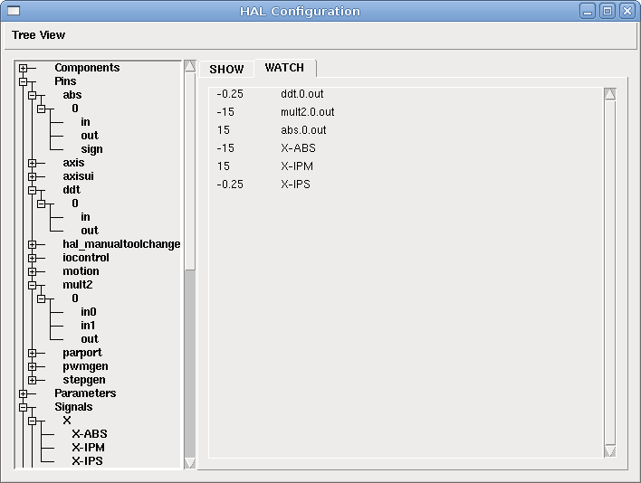
6.3. Soft Start
This example shows how the HAL components "lowpass", "limit2" or "limit3" can be used to limit how fast a signal changes.
In this example we have a servo motor driving a lathe spindle. If we just used the commanded spindle speeds on the servo it will try and go from present speed to commanded speed as fast as it can. This could cause a problem or damage the drive. To slow the rate of change we can send the motion.spindle-speed-out through a limiter before the PID, so that the PID command value varies slowly.
Three built-in components that limit a signal are:
- limit2
-
limits the range and first derivative of a signal.
- limit3
-
limits the range, first and second derivatives of a signal.
- lowpass
-
uses an exponentially-weighted moving average to track an input signal.
To find more information on these HAL components check the man pages.
Place the following in a text file called softstart.hal. If you’re not familiar with Linux place the file in your home directory.
############################## +
loadrt threads period1=1000000 name1=thread  +
loadrt siggen  +
loadrt lowpass  +
loadrt limit2  +
loadrt limit3  +
net square siggen.0.square => lowpass.0.in limit2.0.in limit3.0.in  +
net lowpass <= lowpass.0.out  +
net limit2 <= limit2.0.out  +
net limit3 <= limit3.0.out  +
setp siggen.0.frequency .1  +
setp lowpass.0.gain .01  +
setp limit2.0.maxv 2  +
setp limit3.0.maxv 2  +
setp limit3.0.maxa 10  +
addf siggen.0.update thread  +
addf lowpass.0 thread  +
addf limit2.0 thread  +
addf limit3.0 thread  +
start  +
loadusr halscope +
##############################
Open a terminal window and run the file with the following command.
halrun -I softstart.hal
When the HAL Oscilloscope first starts up click "OK" to accept the default thread.
Next you have to add the signals to the channels. Click on channel 1 then select "square" from the Signals tab. Repeat for channels 2-4 and add lowpass, limit2, and limit3.
Next to set up a trigger signal click on the Source None button and select square. The button will change to Source Chan 1.
Next click on Single in the Run Mode radio buttons box. This will start a run and when it finishes you will see your traces.
To separate the signals so you can see them better click on a channel then use the Pos slider in the Vertical box to set the positions.
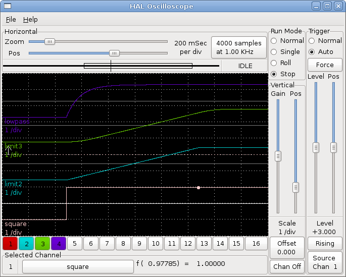
To see the effect of changing the set point values of any of the components you can change them in the terminal window. To see what different gain settings do for lowpass just type the following in the terminal window and try different settings.
setp lowpass.0.gain .01
After changing a setting run the oscilloscope again to see the change.
When you’re finished type "exit" in the terminal window to shut down halrun and close the halscope. Don’t close the terminal window with halrun running as it might leave some things in memory that could prevent EMC from loading.
For more information on HalScope see the HAL manual.
7. Virtual Control Panel
Python Virtual Control Panel
7.1. Introduction
The pyVCP (python Virtual Control Panel) is designed to give the integrator the ability to customize the AXIS interface with buttons and indicators to do special tasks.
Hardware machine control panels can use up a lot of I/O pins and can be expensive. That is where Virtual Control Panels have the advantage as well as it cost nothing to build a pyVCP.
Virtual control panels can be used for testing or monitoring things to temporarily replace real I/O devices while debugging ladder logic, or to simulate a physical panel before you build it and wire it to an I/O board.
The following graphic displays many of the pyVCP widgets.
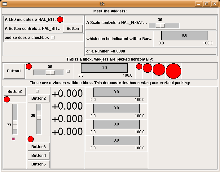
7.2. Panel Construction
The layout of a pyVCP panel is specified with an XML file that contains widget tags between <pyvcp> and </pyvcp>. For example:
<pyvcp>
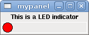
If you place this text in a file called tiny.xml, and run
halrun -I loadusr pyvcp -c mypanel tiny.xml
pyVCP will create the panel for you, which includes two widgets, a Label with the text "This is a LED indicator", and a LED, used for displaying the state of a HAL BIT signal. It will also create a HAL component named "mypanel" (all widgets in this panel are connected to pins that start with "mypanel."). Since no <halpin> tag was present inside the <led> tag, pyVCP will automatically name the HAL pin for the LED widget mypanel.led.0
For a list of widgets and their tags and options, see the widget reference below.
Once you have created your panel, connecting HAL signals to and from the pyVCP pins is done with the halcmd:
net <signal-name> <pin-name> <opt-direction> <opt-pin-name>signal-name
If you are new to HAL, the HAL basics chapter in the Integrators Manual is a good place to start.
7.3. Security
Parts of pyVCP files are evaluated as Python code, and can take any action available to Python programs. Only use pyVCP .xml files from a source that you trust.
7.4. AXIS
Since AXIS uses the same GUI toolkit (Tkinter) as pyVCP, it is possible to include a pyVCP panel on the right side of the normal AXIS user interface. A typical example is explained below.
Place your pyVCP XML file describing the panel in the same directory where your .ini file is. Say we we want to display the current spindle speed using a Bar widget. Place the following in a file called spindle.xml:
<pyvcp>
Here we’ve made a panel with a Label and a Bar widget, specified that the HAL pin connected to the Bar should be named "spindle-speed", and set the maximum value of the bar to 5000 (see widget reference below for all options). To make AXIS aware of this file, and call it at start up, we need to specify the following in the [DISPLAY] section of the .ini file:
PYVCP = spindle.xml
To make our widget actually display the spindle-speed it needs to be hooked up to the appropriate HAL signal. A .hal file that will be run once AXIS and pyVCP have started can be specified in the [HAL] section of the .ini file:
POSTGUI_HALFILE = spindle_to_pyvcp.hal
This change will run the HAL commands specified in "spindle_to_pyvcp.hal". In our example the contents could look like this:
net spindle-rpm-filtered => pyvcp.spindle-speed
assuming that a signal called "spindle-rpm-filtered" already exists. Note that when running together with AXIS, all pyVCP widget HAL pins have names that start with "pyvcp.".
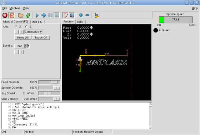
This is what the newly created pyVCP panel should look like in AXIS. The sim/lathe configuration is already configured this way.
7.5. Stand Alone
This section describes how pyVCP panels can be displayed on their own with or without EMC’s machine controller.
To load a stand alone pyVCP panel with EMC use these commands:
loadusr -Wn mypanel pyvcp -g WxH+X+Y -c mypanel <path/>panel_file.xml
You would use this if you wanted a floating panel or a panel with a GUI other than AXIS.
- -Wn panelname
-
makes HAL wait for the component "panelname" to finish loading ("become ready" in HAL speak) before processing more HAL commands. This is important because pyVCP panels export HAL pins and other HAL components will need them present to connect to them. Note the capital W and lowercase n. If you use the -Wn option you must use the -c option to name the panel.
- pyvcp ←g> ←c> panel.xml
-
builds the panel with the optional geometry and/or panelname from the xml panel file. The panel.xml can be any name that ends in .xml. The .xml file is the file that describes how to build the panel. You must add the path name if the panel is not in the directory that the HAL script is in.
- -g <WxH><+X+Y>
-
specifies the geometry to be used when constructing the panel. The syntax is "Width"x"Height""X Anchor""Y Anchor". You can set the size or position or both. The anchor point is the upper left corner of the panel. An example is -g 250x500+800+0 This sets the panel at 250 pixels wide, 500 pixels tall, and anchors it at X800 Y0.
- -c panelname
-
tells pyVCP what to call the component and also the title of the window. The panelname can be any name without spaces.
To load a "stand alone" pyVCP panel without EMC use this command:
loadusr -Wn mypanel pyvcp -g 250x500+800+0 -c mypanel mypanel.xml
The minimum command to load a pyvcp panel is:
loadusr pyvcp mypanel.xml
You would use this if you want a panel without EMC’s machine controller such as for testing or a standalone DRO.
The loadusr command is used when you also load a component that will stop HAL from closing until it’s done. If you loaded a panel and then loaded ClassicLadder using -w ClassicLadder CL would hold HAL open (and the panel) until you closed CL -Wn means wait for the component "panelname" to become ready. "panelname" can be any name. note the capital W and lowercase n. The -c tells pyVCP to build a panel with the name "panelname" using the info in "panel_file_name.xml" "panel_file_name.xml" can be any name but must end in .xml - it is the file that describes how to build the panel. You must add the path name if the panel is not in the directory that the HAL script is in.
An optional command to use if you want the panel to stop HAL from continuing commands / shutting down. After loading any other components you want the last HAL command to be:
waituser panelname
This tells HAL to wait for component "panelname" to close before continuing HAL commands This is usually set as the last command so that HAL shuts down when the panel is closed.
7.6. Widgets
HAL signals come in two variants, bits and numbers. Bits are off/on signals. Numbers can be "float", "s32" or "u32". For more information on HAL data types see the [sec:Hal-Data] section. The pyVCP widget can either display the value of the signal with an indicator widget, or modify the signal value with a control widget. Thus there are four classes of pyVCP widgets that you can connect to a HAL signal. A fifth class of helper widgets allow you to organize and label your panel.
-
Widgets for indicating "bit" signals: led, rectled
-
Widgets for controlling "bit" signals: button, checkbutton, radiobutton
-
Widgets for indicating "number" signals: number, s32, u32, bar, meter
-
Widgets for controlling "number" signals: spinbox, scale, jogwheel
-
Helper widgets: hbox, vbox, table, label, labelframe
Syntax
Each widget is described briefly, followed by the markup used, and a screen shot. All tags inside the main widget tag are optional.
General Notes
At the present time, both a tag-based and an attribute-based syntax are supported. For instance, the following XML fragments are treated identically:
<led halpin="my-led"/>
and
<led><halpin>"my-led"</halpin></led>
When the attribute-based syntax is used, the following rules are used to turn the attributes value into a Python value:
-
If the first character of the attribute is one of the following, it is evaluated as a Python expression: {(["'
-
If the string is accepted by int(), the value is treated as an integer
-
If the string is accepted by float(), the value is treated as floating-point
-
Otherwise, the string is accepted as a string.
When the tag-based syntax is used, the text within the tag is always evaluated as a Python expression.
The examples below show a mix of formats.
Comments
To add a comment use the xml syntax for a comment.
<!-- My Comment -->
Editing the XML file
Edit the XML file with a text editor. In most cases you can right click on the file and select "open with text editor" or similar.
Colors
Colors can be specified using the X11 rgb colors by name "gray75" or hex "#0000ff”. A complete list is located here http://sedition.com/perl/rgb.html.
Common Colors (colors with numbers indicate shades of that color)
-
white
-
black
-
blue and blue1 - 4
-
cyan and cyan1 - 4
-
green and green1 - 4
-
yellow and yellow1 - 4
-
red and red1 - 4
-
purple and purple1 - 4
-
gray and gray0 - 100
HAL Pins
HAL pins provide a means to "connect" the widget to something. Once you create a HAL pin for your widget you can "connect" it to another HAL pin with a "net" command in a .hal file. For more information on the "net" command see the HAL Commands section ( [sec:Hal-Commands]).
7.6.1. Label
A label is a piece of text on your panel.
The label has an optional disable pin that is created when you add <disable_pin>True</disable_pin>.
<label>
The above code produced this example.

7.6.2. LEDs
A LED is used to indicate the status of a "bit" halpin. The LED color will be on_color when the halpin is true, and off_color otherwise.
- <halpin>
-
sets the name of the pin, default is "led.n", where n is an integer
- <size>
-
sets the size of the led, default is 20
- <on_color>
-
sets the color of the LED when the pin is true. default is "green"
- <off_color>
-
sets the color of the LED when the pin is false. default is "red"
- <disable_pin>
-
when true adds a disable pin to the led.
- <disabled_color>
-
sets the color of the LED when the pin is disabled.
Round LED
<led>
The above code produced this example.

Rectangle LED
This is a variant of the "led" widget.
<vbox>
The above code produced this example.
Also showing a vertical box with relief.
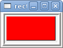
7.6.3. Buttons
A button is used to control a BIT pin. The pin will be set True when the button is pressed and held down, and will be set False when the button is released. Buttons can use the following formatting options
- <padx>n</padx>
-
where "n" is the amount of extra horizontal extra space
- <pady>n</pady>
-
where "n" is the amount of extra vertical extra space
- <activebackground>"color"</activebackground>
-
the cursor over color
- <bg>"color"</bg>
-
the color of the button
Text Button
A text button controls a "bit" halpin. The halpin is false until the button is pressed then it is true. The button is a momentary button.
The text button has an optional disable pin that is created when you add <disable_pin>True</disable_pin>.
<button>
The above code produced this example.

Checkbutton
A checkbutton controls a "bit" halpin. The halpin will be set True when the button is checked, and false when the button is unchecked. The checkbutton is a toggle type button.
<checkbutton>
The above code produced this example.
The coolant checkbutton is checked.
Notice the extra spaces in the Chips text
to keep the checkbuttons aligned.

Radiobutton
A radiobutton will set one of the halpins true. The other pins are set false.
<radiobutton>
The above code produced this example.

Note that the HAL pins in the example above will me named my-radio.one, my-radio.two, and my-radio.three. In the image above, "one" is the selected value.
7.6.4. Number Displays
Number displays can use the following formatting options
-
<font>("Font Name",n)</font> where "n" is the font size
-
<width>n</width> where "n" is the overall width of the space used
-
<justify>pos</justify> where "pos" is LEFT, CENTER, or RIGHT (doesn’t work)
-
<padx>n</padx> where "n" is the amount of extra horizontal extra space
-
<pady>n</pady> where "n" is the amount of extra vertical extra space
Number
The number widget displays the value of a float signal.
<number>
The above code produced this example.
<font> is a Tkinter font type and size specification. One font that will show up to at least size 200 is "courier 10 pitch", so for a really big Number widget you could specify:
<font>("courier 10 pitch",100)</font>
- <format>
-
is a "C-style" format specified that determines how the number is displayed.
s32 Number
The s32 number widget displays the value of a s32 number. The syntax is the same as "number" except the name which is <s32>. Make sure the width is wide enough to cover the largest number you expect to use.
<s32>
The above code produced this example.
u32 Number
The u32 number widget displays the value of a u32 number. The syntax is the same as "number" except the name which is <u32>.
Bar
A bar widget displays the value of a FLOAT signal both graphically using a bar display and numerically.
<bar>
The above code produced this example.
Meter
Meter displays the value of a FLOAT signal using a traditional dial indicator.
<meter>
The above code produced this example.
7.6.5. Number Inputs
Spinbox
Spinbox controls a FLOAT pin. You increase or decrease the value of the pin by either pressing on the arrows, or pointing at the spinbox and rolling your mouse-wheel.
<spinbox>
The above code produced this example.
Scale
Scale controls a float or a s32 pin. You increase or decrease the value of the pin be either dragging the slider, or pointing at the scale and rolling your mouse-wheel. The "halpin" will have both "-f" and "-i" added to it to form the float and s32 pins. Width is the width of the slider in vertical and the height of the slider in horizontal orientation.
<scale>
<scale>
The above code produced this example.

Dial
The Dial outputs a HAL float and reacts to both mouse wheel and dragging. Double left click to increase the resolution and double right click to reduce the resolution by one digit. The output is capped by the min and max values. The <cpr> is how many tick marks are on the outside of the ring (beware of high numbers).
<dial>
The above code produced this example.
Jogwheel
Jogwheel mimics a real jogwheel by outputting a FLOAT pin which counts up or down as the wheel is turned, either by dragging in a circular motion, or by rolling the mouse-wheel.
<jogwheel>
The above code produced this example.
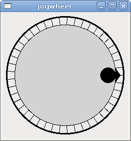
7.6.6. Images
Image displays use only .gif image format. All of the images must be the same size. The images must be in the same directory as your ini file (or in the current directory if running from the command line with halrun/halcmd).
Image Bit
The "image_bit" toggles between two images by setting the halpin to true or false.
<image name='fwd' file='fwd.gif'/>
This example was produced from the above code.
Using the two image files fwd.gif and rev.gif.
FWD is displayed when "selectimage" is false
and REV is displayed when "selectimage" is true.


Image u32
The "image_u32" is the same as "image_bit" except you have essentially an unlimited number of images and you "select" the image by setting the halpin to a integer value with 0 for the first image in the images list and 1 for the second image etc.
<image name='stb' file='stb.gif'/>
The above code produced the following example
by adding the stb.gif image.

Notice that the default is the min even though it is set higher than max unless there is a negative min.
7.6.7. Containers
Containers are widgets that contain other widgets. Containers are used to group other widgets.
Borders
Container borders are specified with two tags used together. The <relief> tag specifies the type of border and the <bd> specifies the width of the border.
- <relief>type</relief>
-
Where "type" is FLAT, SUNKEN, RAISED, GROOVE, or RIDGE
- <bd>n</bd>
-
Where "n" is the width of the border.
<hbox>
    <button>
    <button>
    <button>
    <button>
The above code produced this example.

Hbox
Use a Hbox when you want to stack widgets horizontally next to each other.
<hbox>
The above code produced this example.
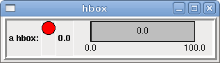
Inside a Hbox, you can use the <boxfill fill=""/>, <boxanchor anchor=""/>, and <boxexpand expand=""/> tags to choose how items in the box behave when the window is re-sized. For details of how fill, anchor, and expand behave, refer to the Tk pack manual page, pack(3tk). By default, fill="y", anchor="center", expand="yes".
Vbox
Use a Vbox when you want to stack widgets vertically on top of each other.
<vbox>
The above code produced this example.
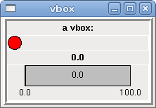
Inside a Hbox, you can use the <boxfill fill=""/>, <boxanchor anchor=""/>, and <boxexpand expand=""/> tags to choose how items in the box behave when the window is re-sized. For details of how fill, anchor, and expand behave, refer to the Tk pack manual page, pack(3tk). By default, fill="x", anchor="center", expand="yes".
Labelframe
A labelframe is a frame with a groove and a label at the upper-left corner.
<labelframe text="Group Title">
The above code produced this example.
Table
A table is a container that allows layout in a grid of rows and columns. Each row is started by a <tablerow/> tag. A contained widget may span rows or columns through the use of the <tablespan rows= cols=/> tag. The sides of the cells to which the contained widgets “stick” may be set through the use of the <tablesticky sticky=/> tag. A table expands on its flexible rows and columns.
Example:
<table flexible_rows="[2]" flexible_columns="[1,4]">
The above code produced this example.
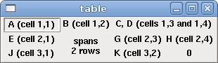
Tabs
A tabbed interface can save quite a bit of space.
<tabs>
The above code produced this example showing each tab selected.
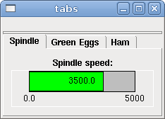
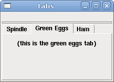
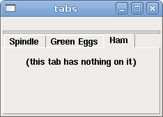
8. VCP Examples
8.1. AXIS
To create a pyVCP panel to use with the AXIS interface that is attached to the right of AXIS you need to do the following basic things.
-
Create an .xml file that contains your panel description and put it in your config directory.
-
Add the PYVCP entry to the [DISPLAY] section of the ini file with your .xml file name.
-
Add the POSTGUI_HALFILE entry to the [HAL] section of the ini file with the name of your postgui hal file name.
-
Add the links to HAL pins for your panel in the postgui.hal file to "connect" your pyVCP panel to EMC.
8.2. Floating
To create floating pyVCP panels that can be used with any interface you need to do the following basic things.
-
Create an .xml file that contains your panel description and put it in your config directory.
-
Add a loadusr line to your .hal file to load each panel.
-
Add the links to HAL pins for your panel in the postgui.hal file to "connect" your pyVCP panel to EMC.
The following is an example of a loadusr command to load two pyVCP panels and name each one so the connection names in HAL will be known.
loadusr -Wn btnpanel pyvcp -c btnpanel panel1.xml +
loadusr -Wn sppanel pyvcp -c sppanel panel2.xml
The -Wn makes hal "Wait for name" to be loaded before proceeding. The pyvcp -c makes pyVCP name the panel.
The HAL pins from panel1.xml will be named btnpanel.<pin name>
The HAL pins from panel2.xml will be named sppanel.<pin name>
Make sure the loadusr line is before any net’s that make use of the pyVCP pins.
8.3. Jog Buttons
In this example we will create a pyVCP panel with jog buttons for X, Y, and Z. This configuration will be built upon a Stepconf Wizard generated configuration. First we run the Stepconf Wizard and configure our machine, then on the Advanced Configuration Options page we make a couple of selections to add a blank pyVCP panel as shown in the following figure. For this example we named the configuration "pyvcp_xyz" on the Basic Machine Information page of the Stepconf Wizard.
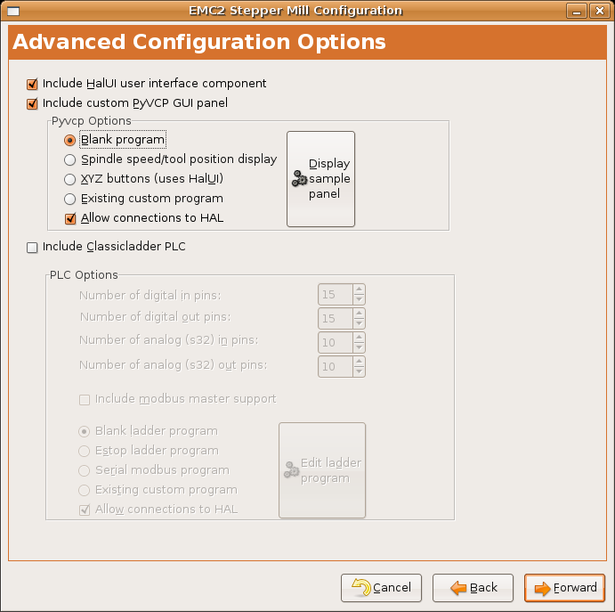
The Stepconf Wizard will create several files and place them in the /emc/configs/pyvcp_xyz directory. If you left the create link checked you will have a link to those files on your desktop.
8.3.1. Create the Widgets
Open up the custompanel.xml file by right clicking on it and selecting "open with text editor". Between the <pyvcp></pyvcp> tags we will add the widgets for our panel.
Look in the pyVCP Widgets Reference section of the manual for more detailed information on each widget.
In your custompanel.xml file we will add the description of the widgets.
<pyvcp>
<labelframe text="Jog Buttons"> +
<font>("Helvetica",16)</font>
<!--- the X jog buttons ---> +
<hbox> +
<relief>RAISED</relief> +
<bd>3</bd> +
<button> +
<font>("Helvetica",20)</font> +
<width>3</width> +
<halpin>"x-plus"</halpin> +
<text>"X+"</text> +
</button> +
<button> +
<font>("Helvetica",20)</font> +
<width>3</width> +
<halpin>"x-minus"</halpin> +
<text>"X-"</text> +
</button> +
</hbox>
<!--- the Y jog buttons ---> +
<hbox> +
<relief>RAISED</relief> +
<bd>3</bd> +
<button> +
<font>("Helvetica",20)</font> +
<width>3</width> +
<halpin>"y-plus"</halpin> +
<text>"Y+"</text> +
</button> +
<button> +
<font>("Helvetica",20)</font> +
<width>3</width> +
<halpin>"y-minus"</halpin> +
<text>"Y-"</text> +
</button> +
</hbox>
<!--- the Z jog buttons ---> +
<hbox> +
<relief>RAISED</relief> +
<bd>3</bd> +
<button> +
<font>("Helvetica",20)</font> +
<width>3</width> +
<halpin>"z-plus"</halpin> +
<text>"Z+"</text> +
</button> +
<button> +
<font>("Helvetica",20)</font> +
<width>3</width> +
<halpin>"z-minus"</halpin> +
<text>"Z-"</text> +
</button> +
</hbox>
<!--- the jog speed slider ---> +
<vbox> +
<relief>RAISED</relief> +
<bd>3</bd> +
<label> +
<text>"Jog Speed"</text> +
<font>("Helvetica",16)</font> +
</label> +
<scale> +
<font>("Helvetica",14)</font> +
<halpin>"jog-speed"</halpin> +
<resolution>1</resolution> +
<orient>HORIZONTAL</orient> +
<min_>0</min_> +
<max_>80</max_> +
</scale> +
</vbox>
</labelframe>
</pyvcp>
 After adding the above you now will have a pyVCP panel that looks like
the following attached to the right side of AXIS. It looks nice but it
does not do anything until you "connect" the buttons to halui. If you
get an error when you try and run scroll down to the bottom of the pop
up window and usually the error is a spelling or syntax error and it
will be there.
.Jog Buttons[[cap:Jog-Buttons]]
image::images/xyz_buttons.png[]
8.3.2. Make Connections
To make the connections needed open up your custom_postgui.hal file and add the following.
# connect the X pyVCP buttons +
net my-jogxminus halui.jog.0.minus <= pyvcp.x-minus +
net my-jogxplus halui.jog.0.plus <= pyvcp.x-plus
# connect the Y pyVCP buttons +
net my-jogyminus halui.jog.1.minus <= pyvcp.y-minus +
net my-jogyplus halui.jog.1.plus <= pyvcp.y-plus
# connect the Z pyVCP buttons +
net my-jogzminus halui.jog.2.minus <= pyvcp.z-minus +
net my-jogzplus halui.jog.2.plus <= pyvcp.z-plus
# connect the pyVCP jog speed slider  +
net my-jogspeed halui.jog-speed <= pyvcp.jog-speed-f
After resetting the E-Stop and putting it into jog mode and moving the jog speed slider in the pyVCP panel to a value greater than zero the pyVCP jog buttons should work. You can not jog when running a g code file or while paused or while the MDI tab is selected.
8.4. Port Tester
This example shows you how to make a simple parallel port tester using pyVCP and HAL.
First create the ptest.xml file with the following code to create the panel description.
<!-- Test panel for the parallel port cfg for out -->
This will create the following floating panel which contains a couple of in pins and a couple of out pins.
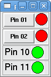
To run the HAL commands that we need to get everything up and running we put the following in our ptest.hal file.
loadrt hal_parport cfg="0x378 out"
To run the HAL file we use the following command from a terminal window.
~$
The following figure shows what a complete panel might look like.
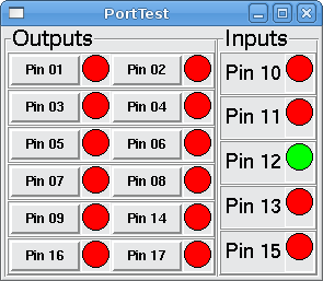
To add the rest of the parallel port pins just modify the .xml and .hal files.
To show the pins after running the HAL script use the following command at the halcmd prompt:
halcmd:
This will show you what pins are IN and what pins are OUT as well as any connections.
8.5. GS2 RPM Meter
The following example uses the Automation Direct GS2 VDF driver and displays the RPM and other info in a pyVCP panel. This example is based on the GS2 example in the Hardware Examples section this manual.
8.5.1. The Panel
To create the panel we add the following to the .xml file.
<pyvcp>
<!-- the RPM meter --> +
<hbox> +
<relief>RAISED</relief> +
<bd>3</bd> +
<meter> +
<halpin>"spindle_rpm"</halpin> +
<text>"Spindle"</text> +
<subtext>"RPM"</subtext> +
<size>200</size> +
<min_>0</min_> +
<max_>3000</max_> +
<majorscale>500</majorscale> +
<minorscale>100</minorscale> +
<region1>0,10,"yellow"</region1> +
</meter> +
</hbox>
<!-- the On Led --> +
<hbox> +
<relief>RAISED</relief> +
<bd>3</bd> +
<vbox> +
<relief>RAISED</relief> +
<bd>2</bd> +
<label> +
<text>"On"</text> +
<font>("Helvetica",18)</font> +
</label> +
<width>5</width> +
 <hbox> +
<label width=”2”/> <!-- used to center the led --> +
<rectled> +
<halpin>"on-led"</halpin> +
<height>"30"</height> +
<width>"30"</width> +
<on_color>"green"</on_color> +
<off_color>"red"</off_color> +
</rectled> +
</hbox> +
</vbox>
<!-- the FWD Led --> +
<vbox> +
<relief>RAISED</relief> +
<bd>2</bd> +
<label> +
<text>"FWD"</text> +
<font>("Helvetica",18)</font> +
<width>5</width> +
</label> +
<label width=”2”/> +
<rectled> +
<halpin>"fwd-led"</halpin> +
<height>"30"</height> +
<width>"30"</width> +
<on_color>"green"</on_color> +
<off_color>"red"</off_color> +
</rectled> +
</vbox>
<!-- the REV Led --> +
<vbox> +
<relief>RAISED</relief> +
<bd>2</bd> +
<label> +
<text>"REV"</text> +
<font>("Helvetica",18)</font> +
<width>5</width> +
</label> +
<label width=”2”/> +
<rectled> +
<halpin>"rev-led"</halpin> +
<height>"30"</height> +
<width>"30"</width> +
<on_color>"red"</on_color> +
<off_color>"green"</off_color> +
</rectled> +
</vbox> +
</hbox> +
</pyvcp>
The above gives us a pyVCP panel that looks like the following.
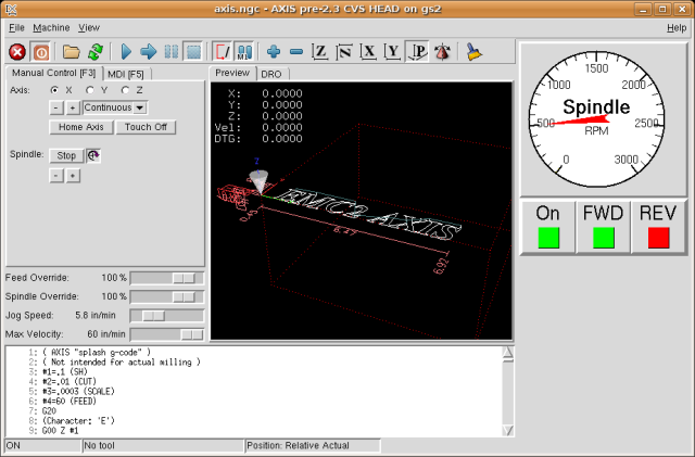
8.5.2. The Connections
To make it work we add the following code to the custom_postgui.hal file.
# display the rpm based on freq * rpm per hz +
loadrt mult2 +
addf mult2.0 servo-thread +
setp mult2.0.in1 28.75 +
net cypher_speed mult2.0.in0 <= spindle-vfd.frequency-out +
net speed_out pyvcp.spindle_rpm <= mult2.0.out
# run led +
net gs2-run => pyvcp.on-led
# fwd led +
net gs2-fwd => pyvcp.fwd-led
# rev led +
net running-rev spindle-vfd.spindle-rev => pyvcp.rev-led
Some of the lines might need some explanations. The fwd led line uses the signal created in the custom.hal file where as the rev led needs to use the spindle-rev bit. You can’t link the spindle-fwd bit twice so you use the signal that it was linked to.
Hardware Drivers
1. AX5214H
The Axiom Measurement & Control AX5214H is a 48 channel digital I/O board. It plugs into an ISA bus, and resembles a pair of 8255 chips. In fact it may be a pair of 8255 chips, but I’m not sure. If/when someone starts a driver for an 8255 they should look at the ax5214 code, much of the work is already done.
1.1. Installing
loadrt hal_ax5214h cfg="<config-string>"
The config string consists of a hex port address, followed by an 8 character string of "I" and "O" which sets groups of pins as inputs and outputs. The first two character set the direction of the first two 8 bit blocks of pins (0-7 and 8-15). The next two set blocks of 4 pins (16-19 and 20-23). The pattern then repeats, two more blocks of 8 bits (24-31 and 32-39) and two blocks of 4 bits (40-43 and 44-47). If more than one board is installed, the data for the second board follows the first. As an example, the string "0x220 IIIOIIOO 0x300 OIOOIOIO" installs drivers for two boards. The first board is at address 0x220, and has 36 inputs (0-19 and 24-39) and 12 outputs (20-23 and 40-47). The second board is at address 0x300, and has 20 inputs (8-15, 24-31, and 40-43) and 28 outputs (0-7. 16-23, 32-39, and 44-47). Up to 8 boards may be used in one system.
1.2. Pins
-
(bit) ax5214.<boardnum>.out-<pinnum> — Drives a physical output pin.
-
(bit) ax5214.<boardnum>.in-<pinnum> — Tracks a physical input pin.
-
(bit) ax5214.<boardnum>.in-<pinnum>-not — Tracks a physical input pin, inverted.
For each pin, <boardnum> is the board number (starts at zero), and <pinnum> is the I/O channel number (0 to 47).
Note that the driver assumes active LOW signals. This is so that modules such as OPTO-22 will work correctly (TRUE means output ON, or input energized). If the signals are being used directly without buffering or isolation the inversion needs to be accounted for. The in- HAL pin is TRUE if the physical pin is low (OPTO-22 module energized), and FALSE if the physical pin is high (OPTO-22 module off). The in-<pinnum>-not HAL pin is inverted — it is FALSE if the physical pin is low (OPTO-22 module energized). By connecting a signal to one or the other, the user can determine the state of the input.
1.3. Parameters
-
(bit) ax5214.<boardnum>.out-<pinnum>-invert — Inverts an output pin.
The -invert parameter determines whether an output pin is active high or active low. If -invert is FALSE, setting the HAL out- pin TRUE drives the physical pin low, turning ON an attached OPTO-22 module, and FALSE drives it high, turning OFF the OPTO-22 module. If -invert is TRUE, then setting the HAL out- pin TRUE will drive the physical pin high and turn the module OFF.
1.4. Functions
-
(funct) ax5214.<boardnum>.read — Reads all digital inputs on one board.
-
(funct) ax5214.<boardnum>.write — Writes all digital outputs on one board.
2. GS2 VFD
This is a userspace HAL program for the GS2 series of VFD’s at Automation Direct.
This component is loaded using the halcmd "loadusr" command:
loadusr -Wn spindle-vfd gs2_vfd -n spindle-vfd +
(loadusr, wait for named to load, component gs2_vfd, named spindle-vfd)
The command-line options are:
-
-b or --bits <n> (default 8) Set number of data bits to <n>, where n must be from 5 to 8 inclusive
-
-d or --device <path> (default /dev/ttyS0) Set the name of the serial device node to use
-
-g or --debug Turn on debugging messages. This will also set the verbose flag. Debug mode will cause all modbus messages to be printed in hex on the terminal.
-
-n or --name <string> (default gs2_vfd) Set the name of the HAL module. The HAL comp name will be set to <string>, and all pin and parameter names will begin with <string>.
-
-p or --parity {even,odd,none} (default odd) Set serial parity to even, odd, or none.
-
-r or --rate <n> (default 38400) Set baud rate to <n>. It is an error if the rate is not one of the following: 110, 300, 600, 1200, 2400, 4800, 9600, 19200, 38400, 57600, 115200
-
-s or --stopbits {1,2} (default 1) Set serial stop bits to 1 or 2
-
-t or --target <n> (default 1) Set MODBUS target (slave) number. This must match the device number you set on the GS2.
-
-v or --verbose Turn on debug messages. Note that if there are serial errors, this may become annoying. At the moment, it doesn’t make much difference most of the time.
Pins where <name> is the name given during loading with the -n option.
-
<name>.DC-bus-volts (float, out) The DC bus voltage of the VFD
-
<name>.at-speed (bit, out) when drive is at commanded speed
-
<name>.err-reset (bit, in) reset errors sent to VFD
-
<name>.firmware-revision (s32, out) from the VFD
-
<name>.frequency-command (float, out) from the VFD
-
<name>.frequency-out (float, out) from the VFD
-
<name>.is-stopped (bit, out) when the VFD reports 0 Hz output
-
<name>.load-percentage (float, out) from the VFD
-
<name>.motor-RPM (float, out) from the VFD
-
<name>.output-current (float, out) from the VFD
-
<name>.output-voltage (float, out) from the VFD
-
<name>.power-factor (float, out) from the VFD
-
<name>.scale-frequency (float, out) from the VFD
-
<name>.speed-command (float, in) speed sent to VFD in RPM
It is an error to send a speed faster than the Motor Max RPM as set in the VFD -
<name>.spindle-fwd (bit, in) 1 for FWD and 0 for REV sent to VFD
-
<name>.spindle-rev (bit, in) 1 for REV and 0 if off
-
<name>.spindle-on (bit, in) 1 for ON and 0 for OFF sent to VFD
-
<name>.status-1 (s32, out) Drive Status of the VFD (see the GS2 manual)
-
<name>.status-2 (s32, out) Drive Status of the VFD (see the GS2 manual)
Note that the value is a sum of all the bits that are on. So a 163 which means
the drive is in the run mode is the sum of 3 (run) + 32 (freq set by serial)
+ 128 (operation set by serial).
Parameters where <name> is the name given during loading with the -n option.
-
<name>.error-count (s32, RW)
-
<name>.loop-time (float, RW) how often the modbus is polled (default 0.1)
-
<name>.nameplate-HZ (float, RW) Nameplate Hz of motor (default 60)
-
<name>.nameplate-RPM (float, RW) Nameplate RPM of motor (default 1730)
-
<name>.retval (s32, RW) the return value of an error in HAL
-
<name>.tolerance (s32, RW) speed tolerance (default 0.01)
An example of using this component to drive a spindle is in the Hardware Examples section of this manual.
3. Mesa HostMot2
3.1. Introduction
HostMot2 is an FPGA configuration developed by Mesa Electronics for their line of "Anything I/O" motion control cards. The firmware is open source, portable and flexible. It can be configured (at compile-time) with zero or more instances (an object created at runtime) of each of several Modules: encoders (quadrature counters), PWM generators, and step/dir generators. The firmware can be configured (at run-time) to connect each of these instances to pins on the I/O headers. I/O pins not driven by a Module instance revert to general-purpose bi-directional digital I/O.
3.2. Firmware Binaries
Several pre-compiled HostMot2 firmware binaries are available for the different Anything I/O boards. (This list is incomplete, check the hostmot2-firmware distribution for up-to-date firmware lists.)
5i20, 5i23, 4i65, 4i68 (72 I/O pins): using hm2_pci module
-
12-channel servo
-
8-channel servo plus 4 step/dir generators
-
4-channel servo plus 8 step/dir generators
5i22 (96 I/O pins): using hm2_pci module
-
16-channel servo
-
8-channel servo plus 24 step/dir generators
3x20 (144 I/O pins): using hm2_pci module
-
24-channel servo
-
16-channel servo plus 24 step/dir generators
7i43 (48 I/O pins): using hm2_7i43 module
-
8-channel servo (8 PWM generators & 8 encoders)
-
4-channel servo plus 4 step/dir generators
3.3. Installing Firmware
Depending on how you installed EMC2 you may have to open the Synaptic Package Manager from the System menu and install the package for your Mesa card. The quickest way to find them is to do a search for "hostmot2" in the Synaptic Package Manager. Mark the firmware for installation then apply.
3.4. Loading HostMot2
The EMC support for the HostMot2 firmware is split into a generic driver called "hostmot2" and two low-level I/O drivers for the Anything I/O boards. The low-level I/O drivers are "hm2_7i43" and "hm2_pci" (for all the PCI- and PC-104/Plus-based AnyIO boards). The hostmot2 driver must be loaded first, using a HAL command like this:
loadrt hostmot2
See the hostmot2(9) man page for details.
The hostmot2 driver by itself does nothing, it needs access to actual boards running the HostMot2 firmware. The low-level I/O drivers provide this access. The low-level I/O drivers are loaded with commands like this:
 loadrt hm2_pci config="firmware=hm2/5i20/SVST8_4.BIT num_encoders=3
num_pwmgens=3 num_stepgens=1"
The config parameters are described in the hostmot2 man page.
3.5. Watchdog
The HostMot2 firmware may include a watchdog Module; if it does, the hostmot2 driver will use it.
The watchdog must be petted by EMC2 periodically or it will bite.
When the watchdog bites, all the board’s I/O pins are disconnected from their Module instances and become high-impedance inputs (pulled high), and all communication with the board stops. The state of the HostMot2 firwmare modules is not disturbed (except for the configuration of the IO Pins). Encoder instances keep counting quadrature pulses, and pwm- and step-generators keep generating signals (which are not relayed to the motors, because the IO Pins have become inputs).
Resetting the watchdog resumes communication and resets the I/O pins to the configuration chosen at load-time.
If the firmware includes a watchdog, the following HAL objects will be exported:
3.5.1. Pins:
 (bit i/o) True if the watchdog has bit, False if the watchdog has not
bit. If the watchdog has bit and the has_bit bit is True, the user can
reset it to False to resume operation.
3.5.2. Parameters:
 (u32 read/write) Watchdog timeout, in nanoseconds. This is initialized
to 1,000,000,000 (1 second) at module load time. If more than this
amount of time passes between calls to the pet_watchdog() function, the
watchdog will bite.
3.5.3. Functions:
- pet_watchdog()
-
Calling this function resets the watchdog timer and postpones the watchdog biting until timeout_ns nanoseconds later. This function should be added to the servo thread.
3.6. HostMot2 Functions
- hm2_<BoardType>.<BoardNum>.read
-
Read all inputs, update input HAL pins.
- hm2_<BoardType>.<BoardNum>.write
-
Write all outputs.
- hm2_<BoardType>.<BoardNum>.pet-watchdog
-
Pet the watchdog to keep it from biting us for a while.
- hm2_<BoardType>.<BoardNum>.read_gpio
-
Read the GPIO input pins. (This function is not available on the 7i43 due to limitations of the EPP bus.)
- hm2_<BoardType>.<BoardNum>.write_gpio
-
Write the GPIO control registers and output pins. (This function is not available on the 7i43 due to limitations of the EPP bus.)
3.7. Pinouts
The hostmot2 driver does not have a particular pinout. The pinout comes from the firmware that the hostmot2 driver sends to the AnyIO board. Each firmware has different pinout, and the pinout depends on how many of the available encoders, pwmgens, and stepgens are used. To get a pinout list for your configuration after loading EMC2 in the terminal window type:
dmesg > hm2.txt
The resulting text file will contain lots of information as well as the pinout for the HostMot2 and any error and warning messages.
To reduce the clutter by clearing the message buffer before loading EMC type the following in the terminal window:
sudo dmesg -c
Now when you run EMC and then do a "dmesg > hm2.txt" in the terminal only the info from the time you loaded EMC will be in your file along with your pinout. The file will be in the current directory of the terminal window. Each line will contain the card name, the card number, the I/O Pin number, the connector and pin, and the usage. From this printout you will know the physical connections to your card based on your configuration.
An example of a 5i20 configuration:
[HOSTMOT2] +
DRIVER=hm2_pci +
BOARD=5i20 +
 CONFIG="firmware=hm2/5i20/SVST8_4.BIT num_encoders=1 num_pwmgens=1
num_stepgens=3"
The above configuration produced this printout .
[ 1141.053386] hm2/hm2_5i20.0: 72 I/O Pins used: +
[ 1141.053394] hm2/hm2_5i20.0: IO Pin 000 (P2-01): IOPort +
[ 1141.053397] hm2/hm2_5i20.0: IO Pin 001 (P2-03): IOPort +
 [ 1141.053401] hm2/hm2_5i20.0: IO Pin 002 (P2-05): Encoder #0, pin B
(Input) +
 [ 1141.053405] hm2/hm2_5i20.0: IO Pin 003 (P2-07): Encoder #0, pin A
(Input) +
[ 1141.053408] hm2/hm2_5i20.0: IO Pin 004 (P2-09): IOPort +
 [ 1141.053411] hm2/hm2_5i20.0: IO Pin 005 (P2-11): Encoder #0, pin
Index (Input) +
[ 1141.053415] hm2/hm2_5i20.0: IO Pin 006 (P2-13): IOPort +
 [ 1141.053418] hm2/hm2_5i20.0: IO Pin 007 (P2-15): PWMGen #0, pin Out0
(PWM or Up) (Output) +
[ 1141.053422] hm2/hm2_5i20.0: IO Pin 008 (P2-17): IOPort +
 [ 1141.053425] hm2/hm2_5i20.0: IO Pin 009 (P2-19): PWMGen #0, pin Out1
(Dir or Down) (Output) +
[ 1141.053429] hm2/hm2_5i20.0: IO Pin 010 (P2-21): IOPort +
 [ 1141.053432] hm2/hm2_5i20.0: IO Pin 011 (P2-23): PWMGen #0, pin
Not-Enable (Output) +
<snip>... +
 [ 1141.053589] hm2/hm2_5i20.0: IO Pin 060 (P4-25): StepGen #2, pin
Step (Output) +
 [ 1141.053593] hm2/hm2_5i20.0: IO Pin 061 (P4-27): StepGen #2, pin
Direction (Output) +
 [ 1141.053597] hm2/hm2_5i20.0: IO Pin 062 (P4-29): StepGen #2, pin
(unused) (Output) +
 [ 1141.053601] hm2/hm2_5i20.0: IO Pin 063 (P4-31): StepGen #2, pin
(unused) (Output) +
 [ 1141.053605] hm2/hm2_5i20.0: IO Pin 064 (P4-33): StepGen #2, pin
(unused) (Output) +
 [ 1141.053609] hm2/hm2_5i20.0: IO Pin 065 (P4-35): StepGen #2, pin
(unused) (Output) +
[ 1141.053613] hm2/hm2_5i20.0: IO Pin 066 (P4-37): IOPort +
[ 1141.053616] hm2/hm2_5i20.0: IO Pin 067 (P4-39): IOPort +
[ 1141.053619] hm2/hm2_5i20.0: IO Pin 068 (P4-41): IOPort +
[ 1141.053621] hm2/hm2_5i20.0: IO Pin 069 (P4-43): IOPort +
[ 1141.053624] hm2/hm2_5i20.0: IO Pin 070 (P4-45): IOPort +
[ 1141.053627] hm2/hm2_5i20.0: IO Pin 071 (P4-47): IOPort +
[ 1141.053811] hm2/hm2_5i20.0: registered +
[ 1141.053815] hm2_5i20.0: initialized AnyIO board at 0000:02:02.0
Note that the IO Pin nnn will correspond to the pin number shown on the HAL Configuration screen for GPIO’s. Some of the Stepgen, Encoder and PWMGen will also show up as GPIO’s in the HAL Configuration screen.
3.8. PIN Files
The default pinout is described in a .PIN file. When you install a firmware package .deb, the .PIN file is installed in
/usr/share/doc/hostmot2-firmware-mesa-<board>-hostmot2
3.9. Firmware
If you are using Run In Place, you must still install a
hostmot2-firmware package.
[The emc2-firmware packages from emc
2.3.x are also compatible with
this version of emc2.
]
3.10. HAL Pins
The HAL pins for each configuration can be seen by opening up "Show HAL Configuration" from the Machine menu. All the HAL pins and parameters can be found there. The following figure is of the 5i20 configuration used above.
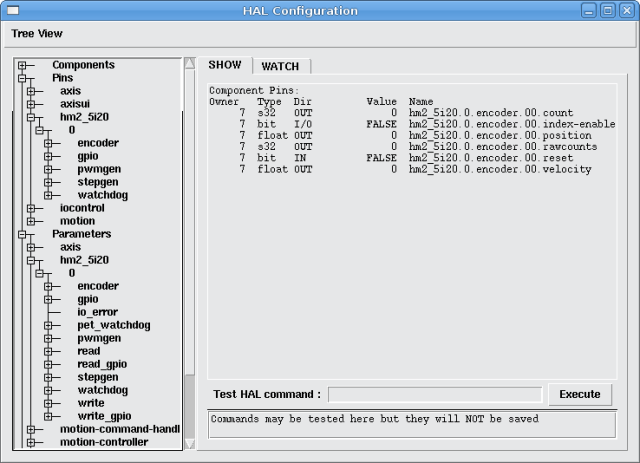
3.11. Configurations
5i20 & 5i23 Default Configurations
| Firmware | 5i20 | 5i23 | Encoder | PWM | StepGen | GPIO |
|---|---|---|---|---|---|---|
SV12 |
X |
X |
12 |
12 |
0 |
0 |
SVST2_8 |
X |
2 |
2 |
8 |
12 |
|
SVST2_4_7I47 |
X |
X |
4 |
2 |
4 |
48 |
SVST4_8 |
X |
4 |
4 |
8 |
0 |
|
SVST8_4 |
X |
X |
8 |
8 |
4 |
0 |
SVST8_4IM2 |
X |
X |
8 |
8 |
4 |
8 |
SVST8_8IM2 |
X |
8 |
8 |
8 |
0 |
4i65 & 4i68 Default Configurations
| Firmware | 4i65 | 4i68 | Encoder | PWM | StepGen | GPIO |
|---|---|---|---|---|---|---|
SV12 |
X |
X |
12 |
12 |
0 |
0 |
SVST4_8 |
X |
4 |
4 |
8 |
0 |
|
SVST8_4 |
X |
X |
8 |
8 |
4 |
0 |
SVST8_4IM2 |
X |
X |
8 |
8 |
4 |
8 |
SVST8_8IM2 |
X |
8 |
8 |
8 |
0 |
7i43 Default Configurations
| Firmware | 200K | 400K | Encoder | PWM | StepGen | GPIO |
|---|---|---|---|---|---|---|
SV8B |
X |
8 |
8 |
0 |
0 |
|
SV8S |
X |
8 |
8 |
0 |
0 |
|
SVST2_4_7I47 |
X |
X |
4 |
2 |
4 |
|
SVST4_4B |
X |
4 |
4 |
4 |
0 |
|
SVST4_4S |
X |
4 |
4 |
4 |
0 |
|
SVST4_6B |
X |
4 |
4 |
6 |
0 |
|
SVST4_6S |
X |
4 |
4 |
6 |
0 |
|
SVST4_12B |
X |
4 |
4 |
12 |
0 |
The 7i43 comes in 200K and 400K gate versions.
Even though several cards may have the same .BIT file you can not use a .BIT file that is not for that card. Different cards have different clock frequencies so make sure you load the proper .BIT file for your card. Custom hm2 firmwares can be created for special applications and you may see some custom hm2 firmwares in the directories with the default ones.
When you load the board-driver (hm2_pci or hm2_7i43), you can tell it to disable instances of the three primary modules (pwmgen, stepgen, and encoder) by setting the count lower. Any I/O pins belonging to disabled module instances become gpios.
3.12. GPIO
General Purpose I/O pins on the board which are not used by a module instance are exported to HAL as "full" GPIO pins. Full GPIO pins can be configured at run-time to be inputs, outputs, or open drains, and have a HAL interface that exposes this flexibility. IO pins that are owned by an active module instance are constrained by the requirements of the owning module, and have a restricted HAL interface.
GPIOs have names like "hm2_<BoardType>.<BoardNum>.gpio.<IONum>." IONum. is a three-digit number. The mapping from IONum to connector and pin-on-that-connector is written to the syslog when the driver loads, and it’s documented in Mesa’s manual for the Anything I/O boards.
The hm2 GPIO representation is modeled after the Digital Inputs and Digital Outputs described in the Canonical Device Interface (part of the HAL General Reference document).
GPIO pins default to input.
3.12.1. Pins
 (Bit, Out) Normal state of the hardware input pin. Both full GPIO pins
and IO pins used as inputs by active module instances have this pin.
 (Bit, Out) Inverted state of the hardware input pin. Both full GPIO
pins and IO pins used as inputs by active module instances have this
pin.
 (Bit, In) Value to be written (possibly inverted) to the hardware
output pin. Only full GPIO pins have this pin.
3.12.2. Parameters
 (Bit, RW) This parameter only has an effect if the "is_output"
parameter is true. If this parameter is true, the output value of the
GPIO will be the inverse of the value on the "out" HAL pin. Only full
GPIO pins and IO pins used as outputs by active module instances have
this parameter. To invert an active module pin you have to invert the
GPIO pin not the module pin.
 (Bit, RW) This parameter only has an effect if the "is_output"
parameter is true. If this parameter is false, the GPIO behaves as a
normal output pin: the IO pin on the connector is driven to the value
specified by the "out" HAL pin (possibly inverted), and the value of
the "in" and "in_not" HAL pins is undefined. If this parameter is true,
the GPIO behaves as an open-drain pin. Writing 0 to the "out" HAL pin
drives the IO pin low, writing 1 to the "out" HAL pin puts the IO pin
in a high-impedance state. In this high-impedance state the IO pin
floats (weakly pulled high), and other devices can drive the value; the
resulting value on the IO pin is available on the "in" and "in_not"
pins. Only full GPIO pins and IO pins used as outputs by active module
instances have this parameter.
 (Bit, RW) If set to 0, the GPIO is an input. The IO pin is put in a
high-impedance state (weakly pulled high), to be driven by other
devices. The logic value on the IO pin is available in the "in" and
"in_not" HAL pins. Writes to the "out" HAL pin have no effect. If this
parameter is set to 1, the GPIO is an output; its behavior then depends
on the "is_opendrain" parameter. Only full GPIO pins have this
parameter.
3.13. StepGen
Stepgens have names like "hm2_<BoardType>.<BoardNum>.stepgen.<Instance>.". "Instance" is a two-digit number that corresponds to the HostMot2 stepgen instance number. There are "num_stepgens" instances, starting with 00.
Each stepgen allocates 2-6 IO pins (selected at firmware compile time), but currently only uses two: Step and Direction outputs.
The stepgen representation is modeled on the stepgen software component. Stepgen default is active high step output (high during step time low during step space). To invert a StepGen output pin you invert the corresponding GPIO pin that is being used by StepGen. To find the GPIO pin being used for the StepGen output run dmesg as shown above.
Each stepgen instance has the following pins and parameters:
3.13.1. Pins
 (Bit, In) Switches between position control mode (0) and velocity
control mode (1). Defaults to position control (0).
(s32, Out) Feedback position in counts (number of steps).
(Bit, In) Enables output steps. When false, no steps are generated.
 (Float, In) Target position of stepper motion, in user-defined
position units.
 (Float, Out) Feedback position in user-defined position units (counts
/ position_scale).
 (Float, In) Target velocity of stepper motion, in user-defined
position units per second. This pin is only used when the stepgen is in
velocity control mode (control-type=1).
 (Float, Out) Feedback velocity in user-defined position units per
second.
3.13.2. Parameters
 (u32, RW) Minimum duration of stable Direction signal after a step
ends, in nanoseconds.
 (u32, RW) Minimum duration of stable Direction signal before a step
begins, in nanoseconds.
 (Float, RW) Maximum acceleration, in position units per second per
second. If set to 0, the driver will not limit its acceleration.
 (Float, RW) Maximum speed, in position units per second. If set to 0,
the driver will choose the maximum velocity based on the values of
steplen and stepspace (at the time that maxvel was set to 0).
 (Float, RW) Converts from counts to position units. position = counts
/ position_scale
 (u32, RW) Output format, like the step_type modparam to the software
stegen(9) component. 0 = Step/Dir, 1 = Up/Down, 2 = Quadrature. In
Quadrature mode (step_type=2), the stepgen outputs one complete Gray
cycle (00 -> 01 -> 11 -> 10 -> 00) for each "step" it takes.
(u32, RW) Duration of the step signal, in nanoseconds.
(u32, RW) Minimum interval between step signals, in nanoseconds.
3.13.3. Output Parameters
The Step and Direction pins of each StepGen have two additional parameters. To find which I/O pin belongs to which step and direction output run dmesg as described above.
 (Bit, RW) This parameter only has an effect if the "is_output"
parameter is true. If this parameter is true, the output value of the
GPIO will be the inverse of the value on the "out" HAL pin.
 (Bit, RW) If this parameter is false, the GPIO behaves as a normal
output pin: the IO pin on the connector is driven to the value
specified by the "out" HAL pin (possibly inverted). If this parameter
is true, the GPIO behaves as an open-drain pin. Writing 0 to the "out"
HAL pin drives the IO pin low, writing 1 to the "out" HAL pin puts the
IO pin in a high-impedance state. In this high-impedance state the IO
pin floats (weakly pulled high), and other devices can drive the value;
the resulting value on the IO pin is available on the "in" and "in_not"
pins. Only full GPIO pins and IO pins used as outputs by active module
instances have this parameter.
3.14. PWMGen
PWMgens have names like "hm2_<BoardType>.<BoardNum>.pwmgen.<Instance>.". "Instance" is a two-digit number that corresponds to the HostMot2 pwmgen instance number. There are "num_pwmgens" instances, starting with 00.
In HM2, each pwmgen uses three output IO pins: Not-Enable, Out0, and Out1. To invert a PWMGen output pin you invert the corresponding GPIO pin that is being used by PWMGen. To find the GPIO pin being used for the PWMGen output run dmesg as shown above.
The function of the Out0 and Out1 IO pins varies with output-type parameter (see below).
The hm2 pwmgen representation is similar to the software pwmgen component. Each pwmgen instance has the following pins and parameters:
3.14.1. Pins
 (Bit, In) If true, the pwmgen will set its Not-Enable pin false and
output its pulses. If "enable" is false, pwmgen will set its Not-Enable
pin true and not output any signals.
(Float, In) The current pwmgen command value, in arbitrary units.
3.14.2. Parameters
 (s32, RW) This emulates the output_type load-time argument to the
software pwmgen component. This parameter may be changed at runtime,
but most of the time you probably want to set it at startup and then
leave it alone. Accepted values are 1 (PWM on Out0 and Direction on
Out1), 2 (Up on Out0 and Down on Out1), 3 (PDM mode, PDM on Out0 and
Dir on Out1), and 4 (Direction on Out0 and PWM on Out1, "for locked
antiphase").
 (Float, RW) Scaling factor to convert "value" from arbitrary units to
duty cycle: dc = value / scale. Duty cycle has an effective range of
-1.0 to +1.0 inclusive, anything outside that range gets clipped.
 (u32, RW) This specifies the PDM frequency, in Hz, of all the pwmgen
instances running in PDM mode (mode 3). This is the "pulse slot
frequency"; the frequency at which the pdm generator in the AnyIO board
chooses whether to emit a pulse or a space. Each pulse (and space) in
the PDM pulse train has a duration of 1/pdm_frequency seconds. For
example, setting the pdm_frequency to 2e6 (2 MHz) and the duty cycle to
50% results in a 1 MHz square wave, identical to a 1 MHz PWM signal
with 50% duty cycle. The effective range of this parameter is from
about 1525 Hz up to just under 100 MHz. Note that the max frequency is
determined by the ClockHigh frequency of the Anything IO board; the
5i20 and 7i43 both have a 100 MHz clock, resulting in a 100 Mhz max PDM
frequency. Other boards may have different clocks, resulting in
different max PDM frequencies. If the user attempts to set the
frequency too high, it will be clipped to the max supported frequency
of the board.
 (u32, RW) This specifies the PWM frequency, in Hz, of all the pwmgen
instances running in the PWM modes (modes 1 and 2). This is the
frequency of the variable-duty-cycle wave. Its effective range is from
1 Hz up to 193 KHz. Note that the max frequency is determined by the
ClockHigh frequency of the Anything IO board; the 5i20 and 7i43 both
have a 100 MHz clock, resulting in a 193 KHz max PWM frequency. Other
boards may have different clocks, resulting in different max PWM
frequencies. If the user attempts to set the frequency too high, it
will be clipped to the max supported frequency of the board.
Frequencies below about 5 Hz are not terribly accurate, but above 5 Hz
they're pretty close.
3.14.3. Output Parameters
The output pins of each PWMGen have two additional parameters. To find which I/O pin belongs to which output run dmesg as described above.
 (Bit, RW) This parameter only has an effect if the "is_output"
parameter is true. If this parameter is true, the output value of the
GPIO will be the inverse of the value on the "out" HAL pin.
 (Bit, RW) If this parameter is false, the GPIO behaves as a normal
output pin: the IO pin on the connector is driven to the value
specified by the "out" HAL pin (possibly inverted). If this parameter
is true, the GPIO behaves as an open-drain pin. Writing 0 to the "out"
HAL pin drives the IO pin low, writing 1 to the "out" HAL pin puts the
IO pin in a high-impedance state. In this high-impedance state the IO
pin floats (weakly pulled high), and other devices can drive the value;
the resulting value on the IO pin is available on the "in" and "in_not"
pins. Only full GPIO pins and IO pins used as outputs by active module
instances have this parameter.
3.15. Encoder
Encoders have names like "hm2_<BoardType>.<BoardNum>.encoder.<Instance>.". "Instance" is a two-digit number that corresponds to the HostMot2 encoder instance number. There are "num_encoders" instances, starting with 00.
Each encoder uses three or four input IO pins, depending on how the firmware was compiled. Three-pin encoders use A, B, and Index (sometimes also known as Z). Four-pin encoders use A, B, Index, and Index-mask.
The hm2 encoder representation is similar to the one described by the Canonical Device Interface (in the HAL General Reference document), and to the software encoder component. Each encoder instance has the following pins and parameters:
3.15.1. Pins
(s32, Out) Number of encoder counts since the previous reset.
 (Bit, I/O) When this pin is set to True, the count (and therefore also
position) are reset to zero on the next Index (Phase-Z) pulse. At the
same time, index-enable is reset to zero to indicate that the pulse has
occurred.
(Float, Out) Encoder position in position units (count / scale).
 (s32, Out) Total number of encoder counts since the start, not
adjusted for index or reset.
 (Bit, In) When this pin is TRUE, the count and position pins are set
to 0. (The value of the velocity pin is not affected by this.) The
driver does not reset this pin to FALSE after resetting the count to 0,
that is the user's job.
(Float, Out) Estimated encoder velocity in position units per second.
3.15.2. Parameters
 (Bit, RW) Set to False (the default) for Quadrature. Set to True for
Up/Down or for single input on Phase A. Can be used for a frequency to
velocity converter with a single input on Phase A when set to true.
 (Bit, RW) If set to True (the default), the quadrature counter needs
15 clocks to register a change on any of the three input lines (any
pulse shorter than this is rejected as noise). If set to False, the
quadrature counter needs only 3 clocks to register a change. The
encoder sample clock runs at 33 MHz on the PCI AnyIO cards and 50 MHz
on the 7i43.
 (Bit, RW) If set to True, the rising edge of the Index input pin
triggers the Index event (if index-enable is True). If set to False,
the falling edge triggers.
 (Bit, RW) If set to True, the Index input pin only has an effect if
the Index-Mask input pin is True (or False, depending on the
index-mask-invert pin below).
 (Bit, RW) If set to True, Index-Mask must be False for Index to have
an effect. If set to False, the Index-Mask pin must be True.
 (Float, RW) Converts from "count" units to "position" units. A
quadrature encoder will normally have 4 counts per pulse so a 100 PPR
encoder would be 400 counts per revolution. In ".counter-mode" a 100
PPR encoder would have 100 counts per revelution as it only uses the
rising edge of A and direction is B.
 (Float, RW) When the encoder is moving slower than one pulse for each
time that the driver reads the count from the FPGA (in the hm2_read()
function), the velocity is harder to estimate. The driver can wait
several iterations for the next pulse to arrive, all the while
reporting the upper bound of the encoder velocity, which can be
accurately guessed. This parameter specifies how long to wait for the
next pulse, before reporting the encoder stopped. This parameter is in
seconds.
3.16. Examples
Several example configurations are included with EMC for both stepper and servo applications. The configurations are located in the hm2-servo and hm2-stepper sections of the EMC2 Configuration Selector window. You will need the same board installed for the configuration you pick to load. The examples are a good place to start and will save you time. Just pick the proper example from the EMC2 Configuration Selector and save a copy to your computer so you can edit it. To see the exact pins and parameters that your configuration gave you open the Show HAL Configuration window from the Machine menu or do dmesg as outlined above.
4. m5i20
|
Note
|
The hal_m5i20 driver is deprecated and you should use the hostmot2 driver for new installations. |
4.1. Mesa Electronics m5i20 "Anything I/O Card"
The Mesa Electronics m5i20 card consists of an FPGA that can be loaded with a wide variety of configurations, and has 72 pins that leave the PC. The assignment of the pins depends on the FPGA configuration. Currently there is a HAL driver for the "4 axis host based motion control" configuration, and this FPGA configurations is also provided with EMC2. It provides 8 encoder counters, 4 PWM outputs (normally used as DACs) and up to 48 digital I/O channels, 32 inputs and 16 outputs.
4.2. Installing
loadrt hal_m5i20 [loadFpga=1|0] [dacRate=<rate>]
If loadFpga is 1 (the default) the driver will load the FPGA configuration on startup. If it is 0, the driver assumes the configuration is already loaded. dacRate sets the carrier frequency for the PWM outputs, in Hz. The default is 32000, for 32KHz PWM. Valid values are from 1 to 32226. The driver prints some useful debugging message to the kernel log, which can be viewed with dmesg.
Up to 4 boards may be used in one system.
4.3. Pins
In the following pins, parameters, and functions, <board> is the board ID. According to the naming conventions the first board should always have an ID of zero, however this driver uses the PCI board ID, so it may be non-zero even if there is only one board.
-
(s32) m5i20.<board>.enc-<channel>-count — Encoder position, in counts.
-
(float) m5i20.<board>.enc-<channel>-position — Encoder position, in user units.
-
(bit) m5i20.<board>.enc-<channel>-index — Current status of index pulse input?
-
(bit) m5i20.<board>.enc-<channel>-index-enable — when true, and an index pulse appears on the encoder input, reset counter to zero and clear index-enable.
-
(bit) m5i20.<board>.enc-<channel>-reset — When true, counter is forced to zero.
-
(bit) m5i20.<board>.dac-<channel>-enable — Enables DAC if true. DAC outputs zero volts if false?
-
(float) m5i20.<board>.dac-<channel>-value — Analog output value for PWM "DAC" (in user units, see -scale and -offset)
-
(bit) m5i20.<board>.in-<channel> — State of digital input pin, see canonical digital input.
-
(bit) m5i20.<board>.in-<channel>-not — Inverted state of digital input pin, see canonical digital input.
-
(bit) m5i20.<board>.out-<channel> — Value to be written to digital output, see canonical digital output.
-
(bit) m5i20.<board>.estop-in — Dedicated estop input, more details needed.
-
(bit) m5i20.<board>.estop-in-not — Inverted state of dedicated estop input.
-
(bit) m5i20.<board>.watchdog-reset — Bidirectional, - Set TRUE to reset watchdog once, is automatically cleared. If bit value 16 is set in watchdog-control then this value is not used, and the hardware watchdog is cleared every time the dac-write function is executed.
4.4. Parameters
-
(float) m5i20.<board>.enc-<channel>-scale — The number of counts / user unit (to convert from counts to units).
-
(float) m5i20.<board>.dac-<channel>-offset — Sets the DAC offset.
-
(float) m5i20.<board>.dac-<channel>-gain — Sets the DAC gain
-
(scaling).
-
(bit) m5i20.<board>.dac-<channel>-interlaced — Sets the DAC to interlaced mode. Use this mode if you are filtering the PWM to generate an anaolg voltage.With normal 10 bit PWM, 50% duty cycle would be 512 cycles on and 512 cycles off = ca 30 kHz with 33 MHz reference counter. With fully interleaved PWM this would be 1 cycle on, 1 cycle off for 1024 cycles (16.66 MHz if the PWM reference counter runs at 33 MHz) = much easier to filter. The 5I20 configuration interlace is somewhat between non and fully interlaced (to make it easy to filter but not have as many transistions as fully interleaved).
-
(bit) m5i20.<board>.out-<channel>-invert — Inverts a digital output, see canonical digital output.
-
(u32) m5i20.<board>.watchdog-control — Configures the watchdog. The value may be a bitwise OR of the following values:
| Bit # | Value | Meaning |
|---|---|---|
0 |
1 |
Watchdog is enabled |
1 |
2 |
Watchdog is automatically reset by DAC writes (the HAL dac-write function) |
Typically, the useful values are 0 (watchdog disabled) or 3 (watchdog enabled, cleared by dac-write).
-
(u32) m5i20.<board>.led-view — Maps some of the I/O to onboard LEDs. See table below.
4.5. Functions
-
(funct) m5i20.<board>.encoder-read — Reads all encoder counters.
-
(funct) m5i20.<board>.digital-in-read — Reads digital inputs.
-
(funct) m5i20.<board>.dac-write — Writes the voltages (PWM duty cycles) to the "DACs".
-
(funct) m5i20.<board>.digital-out-write — Writes digital outputs.
-
(funct) m5i20.<board>.misc-update — Writes watchdog timer configuration to hardware. Resets watchdog timer. Updates E-stop pin (more info needed). Updates onboard LEDs.
4.6. Connector pinout
The Hostmot-4 FPGA configuration has the following pinout. There are three 50-pin ribbon cable connectors on the card: P2, P3, and P4. There are also 8 status LEDs.
4.6.1. Connector P2
| m5i20 Connector P2 | Function/HAL-pin |
|---|---|
1 |
enc-01 A input |
3 |
enc-01 B input |
5 |
enc-00 A input |
7 |
enc-00 B input |
9 |
enc-01 index input |
11 |
enc-00 index input |
13 |
dac-01 output |
15 |
dac-00 output |
17 |
DIR output for dac-01 |
19 |
DIR output for dac-00 |
21 |
dac-01-enable output |
23 |
dac-00-enable output |
25 |
enc-03 B input |
27 |
enc-03 A input |
29 |
enc-02 B input |
31 |
enc-02 A input |
33 |
enc-03 index input |
35 |
enc-02 index input |
37 |
dac-03 output |
39 |
dac-02 output |
41 |
DIR output for dac-03 |
43 |
DIR output for dac-02 |
45 |
dac-03-enable output |
47 |
dac-02-enable output |
49 |
Power +5 V (or +3.3V ?) |
all even pins |
Ground |
4.6.2. Connector P3
Encoder counters 4 - 7 work simultaneously with in-00 to in-11.
If you are using in-00 to in-11 as general purpose IO then reading enc-<4-7> will produce some random junk number.
| m5i20 Connector P3 | Function/HAL-pin | Secondary Function/HAL-pin |
|---|---|---|
1 |
in-00 |
enc-04 A input |
3 |
in-01 |
enc-04 B input |
5 |
in-02 |
enc-04 index input |
7 |
in-03 |
enc-05 A input |
9 |
in-04 |
enc-05 B input |
11 |
in-05 |
enc-05 index input |
13 |
in-06 |
enc-06 A input |
15 |
in-07 |
enc-06 B input |
17 |
in-08 |
enc-06 index input |
19 |
in-09 |
enc-07 A input |
21 |
in-10 |
enc-07 B input |
23 |
in-11 |
enc-07 index input |
25 |
in-12 |
|
27 |
in-13 |
|
29 |
in-14 |
|
31 |
in-15 |
|
33 |
out-00 |
|
35 |
out-01 |
|
37 |
out-02 |
|
39 |
out-03 |
|
41 |
out-04 |
|
43 |
out-05 |
|
45 |
out-06 |
|
47 |
out-07 |
|
49 |
Power +5 V (or +3.3V ?) |
|
all even pins |
Ground |
4.6.3. Connector P4
The index mask masks the index input of the encoder so that the encoder index can be combined with a mechanical switch or opto detector to clear or latch the encoder counter only when the mask input bit is in proper state (selected by mask polarity bit) and encoder index occurs. This is useful for homing. The behaviour of these pins is controlled by the Counter Control Register (CCR), however there is currently no function in the driver to change the CCR. See REGMAP4emc2/src/hal/drivers/m5i20/REGMAP4E for a description of the CCR.
| m5i20 Connector P4 | Function/HAL-pin | Secondary Function/HAL-pin |
|---|---|---|
1 |
in-16 |
enc-00 index mask |
3 |
in-17 |
enc-01 index mask |
5 |
in-18 |
enc-02 index mask |
7 |
in-19 |
enc-03 index mask |
9 |
in-20 |
|
11 |
in-21 |
|
13 |
in-22 |
|
15 |
in-23 |
|
17 |
in-24 |
enc-04 index mask |
19 |
in-25 |
enc-05 index mask |
21 |
in-26 |
enc-06 index mask |
23 |
in-27 |
enc-07 index mask |
25 |
in-28 |
|
27 |
in-29 |
|
29 |
in-30 |
|
31 |
in-31 |
|
33 |
out-08 |
|
35 |
out-09 |
|
37 |
out-10 |
|
39 |
out-11 |
|
41 |
out-12 |
|
43 |
out-13 |
|
45 |
out-14 |
|
47 |
out-15 |
|
49 |
Power +5 V (or +3.3V ?) |
|
all even pins |
Ground |
4.6.4. LEDs
The status LEDs will monitor one motion channel set by the m5i20.<board>.led-view parameter. A call to m5i20.<board>.misc-update is required to update the viewed channel.
| LED name | Output |
|---|---|
LED0 |
IRQLatch ? |
LED1 |
enc-00 index mask |
LED2 |
enc-00 index mask |
LED3 |
enc-<channel> index |
LED4 |
dac-<channel> DIR |
LED5 |
dac-<channel> |
LED6 |
dac-<channel>-enable |
LED7 |
watchdog timeout ? |
5. Motenc
Vital Systems Motenc-100 and Motenc-LITE
The Vital Systems Motenc-100 and Motenc-LITE are 8- and 4-channel servo control boards. The Motenc-100 provides 8 quadrature encoder counters, 8 analog inputs, 8 analog outputs, 64 (68?) digital inputs, and 32 digital outputs. The Motenc-LITE has only 4 encoder counters, 32 digital inputs and 16 digital outputs, but it still has 8 analog inputs and 8 analog outputs. The driver automatically identifies the installed board and exports the appropriate HAL objects.
Installing:
loadrt hal_motenc
During loading (or attempted loading) the driver prints some usefull debugging message to the kernel log, which can be viewed with dmesg.
Up to 4 boards may be used in one system.
5.1. Pins
In the following pins, parameters, and functions, <board> is the board ID. According to the naming conventions the first board should always have an ID of zero. However this driver sets the ID based on a pair of jumpers on the baord, so it may be non-zero even if there is only one board.
-
(s32) motenc.<board>.enc-<channel>-count — Encoder position, in counts.
-
(float) motenc.<board>.enc-<channel>-position — Encoder position, in user units.
-
(bit) motenc.<board>.enc-<channel>-index — Current status of index pulse input.
-
(bit) motenc.<board>.enc-<channel>-idx-latch — Driver sets this pin true when it latches an index pulse (enabled by latch-index). Cleared by clearing latch-index.
-
(bit) motenc.<board>.enc-<channel>-latch-index — If this pin is true, the driver will reset the counter on the next index pulse.
-
(bit) motenc.<board>.enc-<channel>-reset-count — If this pin is true, the counter will immediately be reset to zero, and the pin will be cleared.
-
(float) motenc.<board>.dac-<channel>-value — Analog output value for DAC (in user units, see -gain and -offset)
-
(float) motenc.<board>.adc-<channel>-value — Analog input value read by ADC (in user units, see -gain and -offset)
-
(bit) motenc.<board>.in-<channel> — State of digital input pin, see canonical digital input.
-
(bit) motenc.<board>.in-<channel>-not — Inverted state of digital input pin, see canonical digital input.
-
(bit) motenc.<board>.out-<channel> — Value to be written to digital output, seen canonical digital output.
-
(bit) motenc.<board>.estop-in — Dedicated estop input, more details needed.
-
(bit) motenc.<board>.estop-in-not — Inverted state of dedicated estop input.
-
(bit) motenc.<board>.watchdog-reset — Bidirectional, - Set TRUE to reset watchdog once, is automatically cleared.
5.2. Parameters
-
(float) motenc.<board>.enc-<channel>-scale — The number of counts / user unit (to convert from counts to units).
-
(float) motenc.<board>.dac-<channel>-offset — Sets the DAC offset.
-
(float) motenc.<board>.dac-<channel>-gain — Sets the DAC gain (scaling).
-
(float) motenc.<board>.adc-<channel>-offset — Sets the ADC offset.
-
(float) motenc.<board>.adc-<channel>-gain — Sets the ADC gain (scaling).
-
(bit) motenc.<board>.out-<channel>-invert — Inverts a digital output, see canonical digital output.
-
(u32) motenc.<board>.watchdog-control — Configures the watchdog. The value may be a bitwise OR of the following values:
  [width="90%", options="header"]
  |========================================
  |Bit # | Value | Meaning
  |0 | 1 | Timeout is 16ms if set, 8ms if unset
  |2 | 4 | Watchdog is enabled
   |4 | 16 | Watchdog is automatically reset by DAC writes (the HAL
  dac-write
  function)
  |======================================== +
   Typically, the useful values are 0 (watchdog disabled) or 20 (8ms
  watchdog enabled, cleared by dac-write).
- (u32) motenc.<board>.led-view -- Maps some of the I/O to onboard LEDs?
5.3. Functions
-
(funct) motenc.<board>.encoder-read — Reads all encoder counters.
-
(funct) motenc.<board>.adc-read — Reads the analog-to-digital converters.
-
(funct) motenc.<board>.digital-in-read — Reads digital inputs.
-
(funct) motenc.<board>.dac-write — Writes the voltages to the DACs.
-
(funct) motenc.<board>.digital-out-write — Writes digital outputs.
-
(funct) motenc.<board>.misc-update — Updates misc stuff.
6. OPTO22 PCI
PCI AC5 ADAPTER CARD / HAL DRIVER This page is considered current as of November 2008.
6.1. The Adapter Card
This is a card made by OPTO22 for adapting the PCI port to solid state relay racks such as their standard or G4 series. It has 2 ports that can control up to 24 points each and has 4 on board LEDS. The ports use 50 pin connectors the same as Mesa boards. Any relay racks/breakout boards thats work with Mesa Cards should work with this card with the understanding any encoder counters, pwm etc would have to be done in software- The AC5 does not have any smart logic on board it just an adapter.
See the manufacturer’s website for more info:
I would like to thank OPTO22 for releasing info in their manual, easing the writing of this driver!
6.2. The Driver
This driver is for the PCI ac5 card and will not work with the ISA ac5 card. The HAL driver is a realtime module. It will support 4 cards as is (more cards are possible with a change in the source code). Load the basic driver like so:
loadrt opto_ac5
This will load the driver which will search for max 4 boards.It will set i/o of each board’s 2 ports to a default setting. The default configuration is for 12 inputs then 12 outputs. The pin name numbers correspond to the position on the relay rack. For example the pin names for the default i/o setting of port 0 would be:
opto_ac5.0.port0.in-00 They would be numbered from 00 to 11
opto_ac5.0.port0.out-12 They would be numbered 12 to 23 port 1 would be the same.
6.3. PINS
opto_ac5.[BOARDNUMBER].port[PORTNUMBER].in-[PINNUMBER] OUT bit
opto_ac5.[BOARDNUMBER].port[PORTNUMBER].in-[PINNUMBER]-not OUT bit
Connect a hal bit signal to this pin to read an I/O point from the card. The PINNUMBER represents the position in the relay rack. Eg. PINNUMBER 0 is position 0 in a opto22 relay rack and would be pin 47 on the 50 pin header connector. The -not pin is inverted so that LOW gives TRUE and HIGH gives FALSE.
opto_ac5.[BOARDNUMBER].port[PORTNUMBER].out-[PINNUMBER] IN bit
Connect a hal bit signal to this pin to write to an I/O point of the card. The PINNUMBER represents the position in the relay rack.Eg. PINNUMBER 23 is position 23 in a opto22 relay rack and would be pin 1 on the 50 pin header connector.
opto_ac5.[BOARDNUMBER].led[NUMBER] OUT bit
Turns one of the 4 onboard LEDS on/off. LEDS are numbered 0 to 3.
BOARDNUMBER can be 0-3 PORTNUMBER can be 0 or 1. Port 0 is closest to the card bracket.
6.4. PARAMETERS
opto_ac5.[BOARDNUMBER].port[PORTNUMBER].out-[PINNUMBER]-invert W bit
When TRUE, invert the meaning of the corresponding -out pin so that TRUE gives LOW and FALSE gives HIGH.
6.5. FUNCTIONS
opto_ac5.0.digital-read Add this to a thread to read all the input points.
opto_ac5.0.digital-write Add this to a thread to write all the output points and LEDS.
For example the pin names for the default I/O setting of port 0 would be:
opto_ac5.0.port0.in-00
They would be numbered from 00 to 11
opto_ac5.0.port0.out-12
They would be numbered 12 to 23 port 1 would be the same.
6.6. Configuring I/O Ports
To change the default setting load the driver something like so:
loadrt opto_ac5 portconfig0=0xffff portconfig1=0xff0000
Of course changing the numbers to match the i/o you would like. Each port can be set up different.
Heres how to figure out the number: The configuration number represents a 32 bit long code to tell the card which i/o points are output vrs input. The lower 24 bits are the i/o points of one port. The 2 highest bits are for 2 of the on board LEDS. A one in any bit position makes the i/o point an output. The two highest bits must be output for the LEDS to work. The driver will automatically set the two highest bits for you, we won’t talk about them.
The easiest way to do this is to fire up the calculator under APPLICATIONS/ACCESSORIES. Set it to scientific (click view). Set it BINARY (radio button Bin). Press 1 for every output you want and/or zero for every input. Remember that HAL pin 00 corresponds to the rightmost bit. 24 numbers represent the 24 i/o points of one port. So for the default setting (12 inputs then 12 outputs) you would push 1 twelve times (thats the outputs) then 0 twelve times (thats the inputs). Notice the first i/0 point is the lowest (right most) bit. (that bit corresponds to HAL pin 00 .looks backwards) You should have 24 digits on the screen. Now push the Hex radio button. The displayed number (fff000) is the configport number ( put a 0x in front of it designating it a HEX number).
Another example : to set the port for 8 outputs and 16 inputs (the same as a Mesa card). Here is the 24 bits represented in a BINARY number. Bit 1 is the rightmost number.
000000000000000011111111
16 zeros for the 16 inputs 8 ones for the 8 outputs
Which converts to FF on the calculator so 0xff is the number to use for portconfig0 and/or portconfig1 when loading the driver.
6.7. Pin Numbering
HAL pin 00 corresponds to bit 1 (the rightmost) which represents position 0 on an opto22 relay rack. HAL pin 01 corresponds to bit 2 (one spot to the left of the rightmost) which represents position 1 on an opto22 relay rack. etc. HAL pin 23 corresponds to bit 24 (the leftmost) which represents position 23 on an opto22 relay rack.
Hal pin 00 connects to pin 47 on the 50 pin connector of each port. Hal pin 01 connects to pin 45 on the 50 pin connector of each port. etc. Hal pin 23 connects to pin 1 on the 50 pin connector of each port.
Note that opto22 and Mesa use opposite numbering systems: opto22 position 23 = connector pin 1. and the position goes down as the connector pin number goes up Mesa Hostmot4 position 1 = connector pin 1. and the position number goes up as the connector pin number goes up
7. Pico PPMC
Pico Systems has a family of boards for doing analog servo, stepper, and pwm (digital) servo control. The boards connect to the PC through a parallel port working in EPP mode. Although most users connect one board to a parallel port, in theory any mix of up to 8 or 16 boards can be used on a single parport. One driver serves all types of boards. The final mix of I/O depends on the connected board(s). The driver doesn’t distinguish between boards, it simply numbers I/O channels (encoders, etc) starting from 0 on the first card.
Installing:
loadrt hal_ppmc port_addr=<addr1>[,<addr2>[,<addr3>...]]
The port_addr parameter tells the driver what parallel port(s) to check. By default, <addr1> is 0x0378, and <addr2> and following are not used. The driver searches the entire address space of the enhanced parallel port(s) at port_addr , looking for any board(s) in the PPMC family. It then exports HAL pins for whatever it finds. During loading (or attempted loading) the driver prints some usefull debugging message to the kernel log, which can be viewed with dmesg.
Up to 3 parport busses may be used, and each bus may have up to 8 devices on it.
7.0.1. Pins
In the following pins, parameters, and functions, <board> is the board ID. According to the naming conventions the first board should always have an ID of zero. However this driver sets the ID based on switches on the board, so it may be non-zero even if there is only one board.
-
(All s32` output) ppmc.<port>.encoder.<channel>.count` — Encoder position, in counts.
-
(All s32` output) ppmc.<port>.encoder.<channel>.delta` — Change in counts since last read, in raw encoder count units.
-
(All float output) ppmc.<port>.encoder.<channel>.velocity — Velocity scaled in user units per second. On PPMC and USC this is derived from raw encoder counts per servo period, and hence is affected by encoder granularity. On UPC boards with the 8/21/09 and later firmware, velocity estimation by timestamping encoder counts can be used to improve the smoothness of this velocity output. This can be fed to the pid hal component to produce a more stable servo response. This function has to be enabled in the hal command line that starts the ppmc driver, with the timestamp=0x00 option.
-
(``All float` output) ppmc.<port>.encoder.<channel>.position` — Encoder position, in user units.
-
(All bit ``bidir`) ``ppmc.<port>.encoder.<channel>.index-enable` — Connect to axis.#.index-enable for home-to-index. This is a bidirectional hal signal. Setting it to true causes the encoder hardware to reset the count to zero on the next encoder index pulse. The driver will detect this and set the signal back to false.
-
(UPC bit ``input`) ``ppmc.<port>.pwm.<channel>.enable` — Enables a PWM generator.
-
(UPC float ``input`) ``ppmc.<port>.pwm.<channel>.value` — Value which determines the duty cycle of the PWM waveforms. The value is divided by pwm.<channel>.scale , and if the result is 0.6 the duty cycle will be 60%, and so on. Negative values result in the duty cycle being based on the absolute value, and the direction pin is set to indicate negative.
-
(USC bit ``input`) ``ppmc.<port>.stepgen.<channel>.enable` — Enables a step pulse generator.
-
(USC float ``input`) ``ppmc.<port>.stepgen.<channel>.velocity` — Value which determines the step frequency. The value is multiplied by stepgen.<channel>.scale , and the result is the frequency in steps per second. Negative values result in the frequency being based on the absolute value, and the direction pin is set to indicate negative.
-
(All bit ``output`) ``ppmc.<port>.in-<channel>` — State of digital input pin, see canonical digital input.
-
(All bit ``output`) ``ppmc.<port>.in.<channel>-not` — Inverted state of digital input pin, see canonical digital input.
-
(All bit ``input`) ``ppmc.<port>.out-<channel>` — Value to be written to digital output, seen canonical digital output.
-
(Option float input) ppmc.<port>.DAC8-<channel>.value — Value to be written to analog output, range from 0 to 255. This sends 8 output bits to J8, which should have a Spindle DAC board connected to it. 0 correponds to zero Volts, 255 corresponds to 10 Volts. The polarity of the output can be set for always minus, always plus, or can be controlled by the state of SSR1 (plus when on) and SSR2 (minus when on). You must specify extradac = 0x00 on the hal command line that loads the ppmc driver to enable this function on the first USC ur UPC board.
-
(Option bit input) ppmc.<port>.dout-<channel>.out — Value to be written to one of the 8 extra digital output pins on J8. You must specify extradout = 0x00 on the hal command line that loads the ppmc driver to enable this function on the first USC ur UPC board. extradac and extradout are mutually exclusive features as they use the same signal lines for different purposes.
7.0.2. Parameters
-
(All float) ``ppmc.<port>.enc.<channel>.scale — The number of counts / user unit (to convert from counts to units).
-
(UPC float) ``ppmc.<port>.pwm.<channel-range>.freq — The PWM carrier frequency, in Hz. Applies to a group of four consecutive PWM generators, as indicated by <channel-range>. Minimum is 610Hz, maximum is 500KHz.
-
(``UPC float`) ppmc.<port>.pwm.<channel>.scale` — Scaling for PWM generator. If scale is X, then the duty cycle will be 100% when the value pin is X (or -X).
-
(``UPC float`) ppmc.<port>.pwm.<channel>.max-dc` — Maximum duty cycle, from 0.0 to 1.0.
-
(``UPC float`) ppmc.<port>.pwm.<channel>.min-dc` — Minimum duty cycle, from 0.0 to 1.0.
-
(``UPC float`) ppmc.<port>.pwm.<channel>.duty-cycle` — Actual duty cycle (used mostly for troubleshooting.)
-
(``UPC bit`) ppmc.<port>.pwm.<channel>.bootstrap` — If true, the PWM generator will generate a short sequence of pulses of both polarities when E-stop goes false, to charge the bootstrap capacitors used on some MOSFET gate drivers.
-
(``USC u32`) ppmc.<port>.stepgen.<channel-range>.setup-time` — Sets minimum time between direction change and step pulse, in units of 100nS. Applies to a group of four consecutive PWM generators, as indicated by <channel-range>.
-
(``USC u32`) ppmc.<port>.stepgen.<channel-range>.pulse-width` — Sets width of step pulses, in units of 100nS. Applies to a group of four consecutive PWM generators, as indicated by <channel-range>.
-
(``USC u32`) ppmc.<port>.stepgen.<channel-range>.pulse-space-min` — Sets minimum time between pulses, in units of 100nS. The maximum step rate is 1/( 100nS * ( pulse-width + pulse-space-min )). Applies to a group of four consecutive PWM generators, as indicated by <channel-range>.
-
(``USC float`) ppmc.<port>.stepgen.<channel>.scale` — Scaling for step pulse generator. The step frequency in Hz is the absolute value of velocity * scale.
-
(``USC float`) ppmc.<port>.stepgen.<channel>.max-vel` — The maximum value for velocity. Commands greater than max-vel will be clamped. Also applies to negative values. (The absolute value is clamped.)
-
(``USC float`) ppmc.<port>.stepgen.<channel>.frequency` — Actual step pulse frequency in Hz (used mostly for troubleshooting.)
-
(``Option float`) ppmc.<port>.DAC8.<channel>.scale` — Sets scale of extra DAC output such that an output velue equal to scale gives a magnitude of 10.0 V output. (The sign of the output is set by jumpers and/or other digital outputs.)
-
(``Option bit`) ppmc.<port>.out.<channel>-invert` — Inverts a digital output, see canonical digital output.
-
(``Option bit`) ppmc.<port>.dout.<channel>-invert` — Inverts a digital output pin of J8, see canonical digital output.
7.0.3. Functions
-
(All funct) ``ppmc.<port>.read — Reads all inputs (digital inputs and encoder counters) on one port. These reads are organized into blocks of contiguous registers to be read in a block to minimize CPU overhead.
-
(All funct) ``ppmc.<port>.write — Writes all outputs (digital outputs, stepgens, PWMs) on one port. These reads are organized into blocks of contiguous registers to be read in a block to minimize CPU overhead.
8. Pluto-P
8.1. General Info
The Pluto-P is an inexpensive ($60) FPGA board featuring the ACEX1K chip from Altera.
8.1.1. Requirements
-
A Pluto-P board
-
An EPP-compatible parallel port, configured for EPP mode in the system BIOS
8.1.2. Connectors
-
The Pluto-P board is shipped with the left connector presoldered, with the key in the indicated position. The other connectors are unpopulated. There does not seem to be a standard 12-pin IDC connector, but some of the pins of a 16P connector can hang off the board next to QA3/QZ3.
-
The bottom and right connectors are on the same .1" grid, but the left connector is not. If OUT2…OUT9 are not required, a single IDC connector can span the bottom connector and the bottom two rows of the right connector.
8.1.3. Physical Pins
-
Read the ACEX1K datasheet for information about input and output voltage thresholds. The pins are all configured in "LVTTL/LVCMOS" mode and are generally compatible with 5V TTL logic.
-
Before configuration and after properly exiting emc2, all Pluto-P pins are tristated with weak pull-ups (20kΩ min, 50kΩ max). If the watchdog timer is enabled (the default), these pins are also tristated after an interruption of communication between emc2 and the board. The watchdog timer takes approximately 6.5ms to activate. However, software bugs in the pluto_servo firmware or emc2 can leave the Pluto-P pins in an undefined state.
-
In pwm+dir mode, by default dir is HIGH for negative values and LOW for positive values. To select HIGH for positive values and LOW for negative values, set the corresponding dout-NN-invert parameter TRUE to invert the signal.
-
The index input is triggered on the rising edge. Initial testing has shown that the QZx inputs are particularly noise sensitive, due to being polled every 25ns. Digital filtering has been added to filter pulses shorter than 175ns (seven polling times). Additional external filtering on all input pins, such as a Schmitt buffer or inverter, RC filter, or differential receiver (if applicable) is recommended.
-
The IN1…IN7 pins have 22-ohm series resistors to their associated FPGA pins. No other pins have any sort of protection for out-of-spec voltages or currents. It is up to the integrator to add appropriate isolation and protection. Traditional parallel port optoisolator boards do not work with pluto_servo due to the bidirectional nature of the EPP protocol.
8.1.4. LED
-
When the device is unprogrammed, the LED glows faintly. When the device is programmed, the LED glows according to the duty cycle of PWM0 (LED = UP0 xor DOWN0) or STEPGEN0 (LED = STEP0 xor DIR0).
8.1.5. Power
-
A small amount of current may be drawn from VCC. The available current depends on the unregulated DC input to the board. Alternately, regulated +3.3VDC may be supplied to the FPGA through these VCC pins. The required current is not yet known, but is probably around 50mA plus I/O current.
-
The regulator on the Pluto-P board is a low-dropout type. Supplying 5V at the power jack will allow the regulator to work properly.
8.1.6. PC interface
-
Only a single pluto_servo or pluto_step board is supported.
8.1.7. Rebuilding the FPGA firmware
The src/hal/drivers/pluto_servo_firmware/ and src/hal/drivers/pluto_step_firmware/ subdirectories contain the Verilog source code plus additional files used by Quartus for the FPGA firmwares. Altera’s Quartus II software is required to rebuild the FPGA firmware. To rebuild the firmware from the .hdl and other source files, open the .qpf file and press CTRL-L. Then, recompile emc2.
Like the HAL hardware driver, the FPGA firmware is licensed under the terms of the GNU General Public License.
The gratis version of Quartus II runs only on Microsoft Windows, although there is apparently a paid version that runs on Linux.
8.1.8. For more information
Some additional information about it is available from http://www.fpga4fun.com/board_pluto-P.html and from the developer’s blog.
8.2. pluto-servo: Hardware PWM and quadrature counting
The pluto_servo system is suitable for control of a 4-axis CNC mill with servo motors, a 3-axis mill with PWM spindle control, a lathe with spindle encoder, etc. The large number of inputs allows a full set of limit switches.
This driver features:
-
4 quadrature channels with 40MHz sample rate. The counters operate in "4x" mode. The maximum useful quadrature rate is 8191 counts per emc2 servo cycle, or about 8MHz for EMC2’s default 1ms servo rate.
-
4 PWM channels, "up/down" or "pwm+dir" style. 4095 duty cycles from -100% to +100%, including 0%. The PWM period is approximately 19.5kHz (40MHz / 2047). A PDM-like mode is also available.
-
18 digital outputs: 10 dedicated, 8 shared with PWM functions. (Example: A lathe with unidirectional PWM spindle control may use 13 total digital outputs)
-
20 digital inputs: 8 dedicated, 12 shared with Quadrature functions. (Example: A lathe with index pulse only on the spindle may use 13 total digital inputs)
-
EPP communication with the PC. The EPP communication typically takes around 100uS on machines tested so far, enabling servo rates above 1kHz.
8.2.1. Pinout
- UPx
-
The "up" (up/down mode) or “pwm” (pwm+direction mode) signal from PWM generator X. May be used as a digital output if the corresponding PWM channel is unused, or the output on the channel is always negative. The corresponding digital output invert may be set to TRUE to make UPx active low rather than active high.
- DNx
-
The "down" (up/down mode) or “direction” (pwm+direction mode) signal from PWM generator X. May be used as a digital output if the corresponding PWM channel is unused, or the output on the channel is never negative. The corresponding digital ouput invert may be set to TRUE to make DNx active low rather than active high.
- QAx, QBx
-
The A and B signals for Quadrature counter X. May be used as a digital input if the corresponding quadrature channel is unused.
- QZx
-
The Z (index) signal for quadrature counter X. May be used as a digital input if the index feature of the corresponding quadrature channel is unused.
- INx
-
Dedicated digital input #x
- OUTx
-
Dedicated digital output #x
- GND
-
Ground
- VCC
-
+3.3V regulated DC

| Primary function | Alternate Function | Behavior if both functions used |
|---|---|---|
UP0 |
PWM0 |
When pwm-0-pwmdir is TRUE, this pin is the PWM output |
OUT10 |
XOR’d with UP0 or PWM0 |
|
UP1 |
PWM1 |
When pwm-1-pwmdir is TRUE, this pin is the PWM output |
OUT12 |
XOR’d with UP1 or PWM1 |
|
UP2 |
PWM2 |
When pwm-2-pwmdir is TRUE, this pin is the PWM output |
OUT14 |
XOR’d with UP2 or PWM2 |
|
UP3 |
PWM3 |
When pwm-3-pwmdir is TRUE, this pin is the PWM output |
OUT16 |
XOR’d with UP3 or PWM3 |
|
DN0 |
DIR0 |
When pwm-0-pwmdir is TRUE, this pin is the DIR output |
OUT11 |
XOR’d with DN0 or DIR0 |
|
DN1 |
DIR1 |
When pwm-1-pwmdir is TRUE, this pin is the DIR output |
OUT13 |
XOR’d with DN1 or DIR1 |
|
DN2 |
DIR2 |
When pwm-2-pwmdir is TRUE, this pin is the DIR output |
OUT15 |
XOR’d with DN2 or DIR2 |
|
DN3 |
DIR3 |
When pwm-3-pwmdir is TRUE, this pin is the DIR output |
OUT17 |
XOR’d with DN3 or DIR3 |
|
QZ0 |
IN8 |
Read same value |
QZ1 |
IN9 |
Read same value |
QZ2 |
IN10 |
Read same value |
QZ3 |
IN11 |
Read same value |
QA0 |
IN12 |
Read same value |
QA1 |
IN13 |
Read same value |
QA2 |
IN14 |
Read same value |
QA3 |
IN15 |
Read same value |
QB0 |
IN16 |
Read same value |
QB1 |
IN17 |
Read same value |
QB2 |
IN18 |
Read same value |
QB3 |
IN19 |
Read same value |
8.2.2. Input latching and output updating
-
PWM duty cycles for each channel are updated at different times.
-
Digital outputs OUT0 through OUT9 are all updated at the same time. Digital outputs OUT10 through OUT17 are updated at the same time as the pwm function they are shared with.
-
Digital inputs IN0 through IN19 are all latched at the same time.
-
Quadrature positions for each channel are latched at different times.
8.2.3. HAL Functions, Pins and Parameters
A list of all loadrt arguments, HAL function names, pin names and parameter names is in the manual page, pluto_servo.9.
8.2.4. Compatible driver hardware
A schematic for a 2A, 2-axis PWM servo amplifier board is available (http://emergent.unpy.net/projects/01148303608). The L298 H-Bridge (L298 H-bridge) is inexpensive and can easily be used for motors up to 4A (one motor per L298) or up to 2A (two motors per L298) with the supply voltage up to 46V. However, the L298 does not have built-in current limiting, a problem for motors with high stall currents. For higher currents and voltages, some users have reported success with International Rectifier’s integrated high-side/low-side drivers. (http://www.cnczone.com/forums/showthread.php?t=25929)
8.3. Pluto-step: 300kHz Hardware Step Generator
Pluto-step is suitable for control of a 3- or 4-axis CNC mill with stepper motors. The large number of inputs allows for a full set of limit switches.
The board features:
-
4 “step+direction” channels with 312.5kHz maximum step rate, programmable step length, space, and direction change times
-
14 dedicated digital outputs
-
16 dedicated digital inputs
-
EPP communuication with the PC
8.3.1. Pinout
- STEPx
-
The “step” (clock) output of stepgen channel x
- DIRx
-
The “direction” output of stepgen channel x
- INx
-
Dedicated digital input #x
- OUTx
-
Dedicated digital output #x
- GND
-
Ground
- VCC
-
+3.3V regulated DC
While the “extended main connector” has a superset of signals usually found on a Step & Direction DB25 connector—4 step generators, 9 inputs, and 6 general-purpose outputs—the layout on this header is different than the layout of a standard 26-pin ribbon cable to DB25 connector.

8.3.2. Input latching and output updating
-
Step frequencies for each channel are updated at different times.
-
Digital outputs are all updated at the same time.
-
Digital inputs are all latched at the same time.
-
Feedback positions for each channel are latched at different times.
8.3.3. Step Waveform Timings
The firmware and driver enforce step length, space, and direction change times. Timings are rounded up to the next multiple of 1.6μs, with a maximum of 49.6μs. The timings are the same as for the software stepgen component, except that “dirhold” and “dirsetup” have been merged into a single parameter “dirtime” which should be the maximum of the two, and that the same step timings are always applied to all channels.

8.3.4. HAL Functions, Pins and Parameters
A list of all loadrt arguments, HAL function names, pin names and parameter names is in the manual page, pluto_step.9.
9. Servo-To-Go
The Servo-To-Go is one of the first PC motion control cards supported by EMC. It is an ISA card and it exists in different flavours (all supported by this driver). The board includes up to 8 channels of quadrature encoder input, 8 channels of analog input and output, 32 bits digital I/O, an interval timer with interrupt and a watchdog.
9.0.1. Installing
 loadrt hal_stg [base=<address>] [num_chan=<nr>] [dio="<dio-string>"]
[model=<model>]
The base address field is optional; if it’s not provided the driver attempts to autodetect the board. The num_chan field is used to specify the number of channels available on the card, if not used the 8 axis version is assumed. The digital inputs/outputs configuration is determined by a config string passed to insmod when loading the module. The format consists of a four character string that sets the direction of each group of pins. Each character of the direction string is either "I" or "O". The first character sets the direction of port A (Port A - DIO.0-7), the next sets port B (Port B - DIO.8-15), the next sets port C (Port C - DIO.16-23), and the fourth sets port D (Port D - DIO.24-31). The model field can be used in case the driver doesn’t autodetect the right card version.
hint: after starting up the driver, dmesg can be consulted for messages relevant to the driver (e.g. autodetected version number and base address). For example:
loadrt hal_stg base=0x300 num_chan=4 dio="IOIO"
This example installs the stg driver for a card found at the base
address of 0x300, 4 channels of encoder feedback, DAC’s and ADC’s,
along with 32 bits of I/O configured like this: the first 8 (Port A)
configured as Input, the next 8 (Port  configured as Output, the next
8 (Port C) configured as Input, and the last 8 (Port D) configured as
Output
configured as Output, the next
8 (Port C) configured as Input, and the last 8 (Port D) configured as
Output
loadrt hal_stg
This example installs the driver and attempts to autodetect the board address and board model, it installs 8 axes by default along with a standard I/O setup: Port A & B configured as Input, Port C & D configured as Output.
9.1. Pins
-
stg.<channel>.counts (s32) Tracks the counted encoder ticks.
-
stg.<channel>.position (float) Outputs a converted position.
-
stg.<channel>.dac-value (float) Drives the voltage for the corresponding DAC.
-
stg.<channel>.adc-value (float) Tracks the measured voltage from the corresponding ADC.
-
stg.in-<pinnum> (bit) Tracks a physical input pin.
-
stg.in-<pinnum>-not (bit) Tracks a physical input pin, but inverted.
-
stg.out-<pinnum> (bit) Drives a physical output pin
For each pin, <channel> is the axis number, and <pinnum> is the logic pin number of the STGif IIOO is defined, there are 16 input pins (in-00 .. in-15) and 16 output pins (out-00 .. out-15), and they correspond to PORTs ABCD (in-00 is PORTA.0, out-15 is PORTD.7).
The in- HAL pin is TRUE if the physical pin is high, and FALSE if the physical pin is low. The in-<pinnum>-not HAL pin is inverted — it is FALSE if the physical pin is high. By connecting a signal to one or the other, the user can determine the state of the input.
9.2. Parameters
-
stg.<channel>.position-scale (float) The number of counts / user unit (to convert from counts to units).
-
stg.<channel>.dac-offset (float) Sets the offset for the corresponding DAC.
-
stg.<channel>.dac-gain (float) Sets the gain of the corresponding DAC.
-
stg.<channel>.adc-offset (float) Sets the offset of the corresponding ADC.
-
stg.<channel>.adc-gain (float) Sets the gain of the corresponding ADC.
-
stg.out-<pinnum>-invert (bit) Inverts an output pin.
The -invert parameter determines whether an output pin is active high or active low. If -invert is FALSE, setting the HAL out- pin TRUE drives the physical pin high, and FALSE drives it low. If -invert is TRUE, then setting the HAL out- pin TRUE will drive the physical pin low.
9.2.1. Functions
-
stg.capture-position (funct) Reads the encoder counters from the axis <channel>.
-
stg.write-dacs (funct) Writes the voltages to the DACs.
-
stg.read-adcs (funct) Reads the voltages from the ADCs.
-
stg.di-read (funct) Reads physical in- pins of all ports and updates all HAL in- and in-<pinnum>-not pins.
-
stg.do-write (funct) Reads all HAL out- pins and updates all physical output pins.
Advanced topics
1. Kinematics in EMC2
1.1. Introduction
When we talk about CNC machines, we usually think about machines that are commanded to move to certain locations and perform various tasks. In order to have an unified view of the machine space, and to make it fit the human point of view over 3D space, most of the machines (if not all) use a common coordinate system called the Cartesian Coordinate System.
The Cartesian Coordinate system is composed of 3 axes (X, Y, Z) each
perpendicular to the other 2.
[The word “axes” is also
commonly (and wrongly) used when talking about
CNC machines, and referring to the moving directions of the machine.
]
When we talk about a G-code program (RS274NGC) we talk about a number
of commands (G0, G1, etc.) which have positions as parameters (X- Y-
Z-). These positions refer exactly to Cartesian positions. Part of the
EMC2 motion controller is responsible for translating those positions
into positions which correspond to the machine
kinematics
[Kinematics: a two way function to
transform from Cartesian space to
joint space
]
.
1.1.1. Joints vs. Axes
A joint of a CNC machine is a one of the physical degrees of freedom of the machine. This might be linear (leadscrews) or rotary (rotary tables, robot arm joints). There can be any number of joints on a certain machine. For example a typical robot has 6 joints, and a typical simple milling machine has only 3.
There are certain machines where the joints are layed out to match kinematics axes (joint 0 along axis X, joint 1 along axis Y, joint 2 along axis Z), and these machines are called Cartesian machines (or machines with Trivial Kinematics). These are the most common machines used in milling, but are not very common in other domains of machine control (e.g. welding: puma-typed robots).
1.2. Trivial Kinematics
As we said there is a group of machines in which each joint is placed along one of the Cartesian axes. On these machines the mapping from Cartesian space (the G-code program) to the joint space (the actual actuators of the machine) is trivial. It is a simple 1:1 mapping:
pos->tran.x = joints[0]; +
pos->tran.y = joints[1]; +
pos->tran.z = joints[2]; +
pos->a = joints[3]; +
pos->b = joints[4]; +
pos->c = joints[5];
In the above code snippet one can see how the mapping is done: the X position is identical with the joint 0, Y with joint 1 etc. The above refers to the direct kinematics (one way of the transformation) whereas the next code part refers to the inverse kinematics (or the inverse way of the transformation):
joints[0] = pos->tran.x; +
joints[1] = pos->tran.y; +
joints[2] = pos->tran.z; +
joints[3] = pos->a; +
joints[4] = pos->b; +
joints[5] = pos->c;
As one can see, it’s pretty straightforward to do the transformation
for a trivial kins (or Cartesian) machine. It gets a bit more
complicated if the machine is missing one of the axes.
[If a
machine (e.g. a lathe) is set up with only the axes X,Z & A, and
the EMC2 inifile holds only these 3 joints defined, then the above
matching will be faulty. That is because we actually have (joint0=x,
joint1=Z, joint2=A) whereas the above assumes joint1=Y. To make it
easily work in EMC2 one needs to define all axes (XYZA), then use a
simple loopback in HAL for the unused Y axis.
]
[One other way of making it work, is by changing the
matching code and
recompiling the software.
]
1.3. Non-trivial kinematics
There can be quite a few types of machine setups (robots: puma, scara; hexapods etc.). Each of them is set up using linear and rotary joints. These joints don’t usually match with the Cartesian coordinates, therefor there needs to be a kinematics function which does the conversion (actually 2 functions: forward and inverse kinematics function).
To illustrate the above, we will analyze a simple kinematics called bipod (a simplified version of the tripod, which is a simplified version of the hexapod).
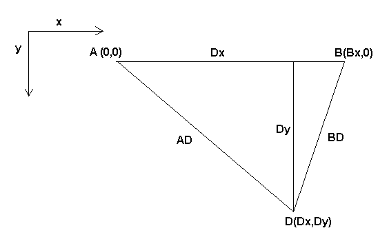
The Bipod we are talking about is a device that consists of 2 motors placed on a wall, from which a device is hanged using some wire. The joints in this case are the distances from the motors to the device (named AD and BD in figure [cap:Bipod-setup]).
The position of the motors is fixed by convention. Motor A is in (0,0), which means that its X coordinate is 0, and its Y coordinate is also 0. Motor B is placed in (Bx, 0), which means that its X coordinate is Bx.
Our tooltip will be in point D which gets defined by the distances AD and BD, and by the Cartesian coordinates Dx, Dy.
The job of the kinematics is to transform from joint lengths (AD, BD) to Cartesian coordinates (Dx, Dy) and vice-versa.
1.3.1. Forward transformation
To transform from joint space into Cartesian space we will use some trigonometry rules (the right triangles determined by the points (0,0), (Dx,0), (Dx,Dy) and the triangle (Dx,0), (Bx,0) and (Dx,Dy).
we can easily see that $AD^{2}=x^{2}+y^{2}$, likewise $BD^{2}=(Bx-x)^{2}+y^{2}$.
If we subtract one from the other we will get:
and therefore:
From there we calculate:
Note that the calculation for y involves the square root of a difference, which may not result in a real number. If there is no single Cartesian coordinate for this joint position, then the position is said to be a singularity. In this case, the forward kinematics return -1.
Translated to actual code:
double AD2 = joints[0] * joints[0]; +
double BD2 = joints[1] * joints[1]; +
double x = (AD2 - BD2 + Bx * Bx) / (2 * Bx); +
double y2 = AD2 - x * x; +
if(y2 < 0) return -1; +
pos->tran.x = x; +
pos->tran.y = sqrt(y2); +
return 0;
1.3.2. Inverse transformation
The inverse kinematics is lots easier in our example, as we can write it directly:
or translated to actual code:
double x2 = pos->tran.x * pos->tran.x; +
double y2 = pos->tran.y * pos->tran.y; +
joints[0] = sqrt(x2 + y2); +
joints[1] = sqrt((Bx - pos->tran.x)*(Bx - pos->tran.x) + y2); +
return 0;
1.4. Implementation details
A kinematics module is implemented as a HAL component, and is permitted to export pins and parameters. It consists of several “C” functions (as opposed to HAL functions):
-
` int kinematicsForward(const double *joint, EmcPose *world, const KINEMATICS_FORWARD_FLAGS *fflags, KINEMATICS_INVERSE_FLAGS *iflags)` Implements the forward kinematics function as described in HAL manual.
-
` int kinematicsInverse(const EmcPose * world, double *joints, const KINEMATICS_INVERSE_FLAGS *iflags, KINEMATICS_FORWARD_FLAGS *fflags)` Implements the inverse kinematics function as described in the HAL manual.
-
KINEMATICS_TYPE kinematicsType(void) Returns the kinematics type identifier, typically KINEMATICS_BOTH.
-
` int kinematicsHome(EmcPose *world, double *joint, KINEMATICS_FORWARD_FLAGS *fflags, KINEMATICS_INVERSE_FLAGS *iflags)` The home kinematics function sets all its arguments to their proper values at the known home position. When called, these should be set, when known, to initial values, e.g., from an INI file. If the home kinematics can accept arbitrary starting points, these initial values should be used.
-
int rtapi_app_main(void)
-
void rtapi_app_exit(void) These are the standard setup and tear-down functions of RTAPI modules.
When they are contained in a single source file, kinematics modules may be compiled and installed by comp. See the comp(1) manpage or the HAL manual for more information.
Tuning
1. Stepper Tuning
1.1. Getting the most out of Software Stepping
Generating step pulses in software has one very big advantage - it’s free. Just about every PC has a parallel port that is capable of outputting step pulses that are generated by the software. However, software step pulses also have some disadvantages:
-
limited maximum step rate
-
jitter in the generated pulses
-
loads the CPU
This chapter has some steps that can help you get the best results from software generated steps.
1.1.1. Run a Latency Test
The new easy way to run a latency test is described in the Getting Started Guide.
Latency is how long it takes the PC to stop what it is doing and respond to an external request. In our case, the request is the periodic "heartbeat" that serves as a timing reference for the step pulses. The lower the latency, the faster you can run the heartbeat, and the faster and smoother the step pulses will be.
Latency is far more important than CPU speed. A lowly Pentium II that responds to interrupts within 10 microseconds each and every time can give better results than the latest and fastest P4 Hyperthreading beast.
The CPU isn’t the only factor in determining latency. Motherboards, video cards, USB ports, and a number of other things can hurt the latency. The best way to find out what you are dealing with is to run the RTAI latency test.
DO NOT TRY TO RUN EMC2 WHILE THE TEST IS RUNNING
On Ubuntu Dapper, you can run the test by opening a shell and doing:
sudo mkdir /dev/rtf;  +
sudo mknod /dev/rtf/3 c 150 3;  +
sudo mknod /dev/rtf3 c 150 3;  +
cd /usr/realtime*/testsuite/kern/latency; ./run
and then you should see something like this:
ubuntu:/usr/realtime-2.6.12-magma/testsuite/kern/latency$ ./run  +
*  +
*  +
* Type ^C to stop this application.  +
*  +
*
## RTAI latency calibration tool ##  +
# period = 100000 (ns)  +
# avrgtime = 1 (s)  +
# do not use the FPU  +
# start the timer  +
# timer_mode is oneshot
RTAI Testsuite - KERNEL latency (all data in nanoseconds)  +
RTH| lat min| ovl min| lat avg| lat max| ovl max| overruns  +
RTD|   -1571|   -1571|    1622|    8446|    8446|      0  +
RTD|   -1558|   -1571|    1607|    7704|    8446|      0  +
RTD|   -1568|   -1571|    1640|    7359|    8446|      0  +
RTD|   -1568|   -1571|    1653|    7594|    8446|      0  +
RTD|   -1568|   -1571|    1640|   10636|   10636|      0  +
RTD|   -1568|  -1571|    1640|   10636|   10636|      0
While the test is running, you should "abuse" the computer. Move windows around on the screen. Surf the web. Copy some large files around on the disk. Play some music. Run an OpenGL program such as glxgears. The idea is to put the PC through its paces while the latency test checks to see what the worst case numbers are.
The last number in the column labeled "ovl max" is the most important. Write it down - you will need it later. It contains the worst latency measurement during the entire run of the test. In the example above, that is 10636 nano-seconds, or 10.6 micro-seconds, which is excellent. However the example only ran for a few seconds (it prints one line every second). You should run the test for at least several minutes; sometimes the worst case latency doesn’t happen very often, or only happens when you do some particular action. I had one Intel motherboard that worked pretty well most of the time, but every 64 seconds it had a very bad 300uS latency. Fortunately that is fixable, see FixingDapperSMIIssues in the wiki found at wiki.linuxcnc.org.
So, what do the results mean? If your "ovl max" number is less than about 15-20 microseconds (15000-20000 nanoseconds), the computer should give very nice results with software stepping. If the max latency is more like 30-50 microseconds, you can still get good results, but your maximum step rate might be a little dissapointing, especially if you use microstepping or have very fine pitch leadscrews. If the numbers are 100uS or more (100,000 nanoseconds), then the PC is not a good candidate for software stepping. Numbers over 1 millisecond (1,000,000 nanoseconds) mean the PC is not a good candidate for EMC, regardless of whether you use software stepping or not.
Note that if you get high numbers, there may be ways to improve them. For example, one PC had very bad latency (several milliseconds) when using the onboard video. But a $5 used Matrox video card solved the problem - EMC does not require bleeding edge hardware.
1.1.2. Figure out what your drives expect
Different brands of stepper drives have different timing requirements on their step and direction inputs. So you need to dig out (or Google for) the data sheet that has your drive’s specs.
For example, the Gecko G202 manual says this:
Step Frequency: 0 to 200 kHz
Step Pulse “0” Time: 0.5 uS min (Step on falling edge)
Step Pulse “1” Time: 4.5 uS min
Direction Setup: 1 uS min (20 uS min hold time after Step edge)
The Gecko G203V specifications are:
Step Frequency: 0 to 333 kHz
Step Pulse “0” Time: 2.0 uS min (Step on rising edge)
Step Pulse “1” Time: 1.0 uS min

Direction Setup:
    200 nS (0.2uS) before step pulse rising edge
    200 nS (0.2uS) hold after step pulse rising edge
A Xylotex drive datasheet has a nice drawing of the timing requirements, which are:
Minimum DIR setup time before rising edge of STEP Pulse 200nS Minimum
DIR hold time after rising edge of STEP pulse 200nS
Minimum STEP pulse high time 2.0uS
Minimum STEP pulse low time 1.0uS
Step happens on rising edge
Once you find the numbers, write them down too - you need them in the next step.
1.1.3. Choose your BASE_PERIOD
BASE_PERIOD is the "heartbeat" of your EMC computer. Every period, the software step generator decides if it is time for another step pulse. A shorter period will allow you to generate more pulses per second, within limits. But if you go too short, your computer will spend so much time generating step pulses that everything else will slow to a crawl, or maybe even lock up. Latency and stepper drive requirements affect the shortest period you can use, as we will see in a minute.
Let’s look at the Gecko example first. The G202 can handle step pulses that go low for 0.5uS and high for 4.5uS, it needs the direction pin to be stable 1uS before the falling edge, and remain stable for 20uS after the falling edge. The longest timing requirement is the 20uS hold time. A simple approach would be to set the period at 20uS. That means that all changes on the STEP and DIR lines are separated by 20uS. All is good, right?
Wrong! If there was ZERO latency, then all edges would be separated by 20uS, and everything would be fine. But all computers have some latency. Latency means lateness. If the computer has 11uS of latency, that means sometimes the software runs as much as 11uS later than it was supposed to. If one run of the software is 11uS late, and the next one is on time, the delay from the first to the second is only 9uS. If the first one generated a step pulse, and the second one changed the direction bit, you just violated the 20uS G202 hold time requirement. That means your drive might have taken a step in the wrong direction, and your part will be the wrong size.
The really nasty part about this problem is that it can be very very rare. Worst case latencies might only happen a few times a minute, and the odds of bad latency happening just as the motor is changing direction are low. So you get very rare errors that ruin a part every once in a while and are impossible to troubleshoot.
The simplest way to avoid this problem is to choose a BASE_PERIOD that is the sum of the longest timing requirement of your drive, and the worst case latency of your computer. If you are running a Gecko with a 20uS hold time requirement, and your latency test said you have a maximum latency of 11uS, then if you set the BASE_PERIOD to 20+11 = 31uS (31000 nano-seconds in the ini file), you are guaranteed to meet the drive’s timing requirements.
But there is a tradeoff. Making a step pulse requires at least two periods. One to start the pulse, and one to end it. Since the period is 31uS, it takes 2x31 = 62uS to create a step pulse. That means the maximum step rate is only 16,129 steps per second. Not so good. (But don’t give up yet, we still have some tweaking to do in the next section.)
For the Xylotex, the setup and hold times are very short, 200nS each (0.2uS). The longest time is the 2uS high time. If you have 11uS latency, then you can set the BASE_PERIOD as low as 11+2=13uS. Getting rid of the long 20uS hold time really helps! With a period of 13uS, a complete step takes 2x13 = 26uS, and the maximum step rate is 38,461 steps per second!
But you can’t start celebrating yet. Note that 13uS is a very short period. If you try to run the step generator every 13uS, there might not be enough time left to run anything else, and your computer will lock up. If you are aiming for periods of less than 25uS, you should start at 25uS or more, run EMC, and see how things respond. If all is well, you can gradually decrease the period. If the mouse pointer starts getting sluggish, and everything else on the PC slows down, your period is a little too short. Go back to the previous value that let the computer run smoothly.
In this case, sppose you started at 25uS, trying to get to 13uS, but you find that around 16uS is the limit - any less and the computer doesn’t respond very well. So you use 16uS. With a 16uS period and 11uS latency, the shortest output time will be 16-11 = 5uS. The drive only needs 2uS, so you have some margin. Margin is good - you don’t want to lose steps because you cut the timing too close.
What is the maximum step rate? Remember, two periods to make a step. You settled on 16uS for the period, so a step takes 32uS. That works out to a not bad 31,250 steps per second.
1.1.4. Use steplen, stepspace, dirsetup, and/or dirhold
In the last section, we got the Xylotex drive to a 16uS period and a 31,250 step per second maximum speed. But the Gecko was stuck at 31uS and a not-so-nice 16,129 steps per second. The Xylotex example is as good as we can make it. But the Gecko can be improved.
The problem with the G202 is the 20uS hold time requirement. That plus the 11uS latency is what forces us to use a slow 31uS period. But the EMC2 software step generator has some parameters that let you increase the various time from one period to several. For example, if steplen is changed from 1 to 2, then it there will be two periods between the beginning and end of the step pulse. Likewise, if dirhold is changed from 1 to 3, there will be at least three periods between the step pulse and a change of the direction pin.
If we can use dirhold to meet the 20uS hold time requirement, then the next longest time is the 4.5uS high time. Add the 11uS latency to the 4.5uS high time, and you get a minimum period of 15.5uS. When you try 15.5uS, you find that the computer is sluggish, so you settle on 16uS. If we leave dirhold at 1 (the default), then the minimum time between step and direction is the 16uS period minus the 11uS latency = 5uS, which is not enough. We need another 15uS. Since the period is 16uS, we need one more period. So we change dirhold from 1 to 2. Now the minimum time from the end of the step pulse to the changing direction pin is 5+16=21uS, and we don’t have to worry about the Gecko stepping the wrong direction because of latency.
If the computer has a latency of 11uS, then a combination of a 16uS base period, and a dirhold value of 2 ensures that we will always meet the timing requirements of the Gecko. For normal stepping (no direction change), the increased dirhold value has no effect. It takes two periods totalling 32uS to make each step, and we have the same 31,250 step per second rate that we got with the Xylotex.
The 11uS latency number used in this example is very good. If you work through these examples with larger latency, like 20 or 25uS, the top step rate for both the Xylotex and the Gecko will be lower. But the same formulas apply for calculating the optimum BASE_PERIOD, and for tweaking dirhold or other step generator parameters.
1.1.5. No Guessing!
For a fast AND reliable software based stepper system, you cannot just guess at periods and other configuration paremeters. You need to make measurements on your computer, and do the math to ensure that your drives get the signals they need.
To make the math easier, I’ve created an Open Office spreadsheet
http://wiki.linuxcnc.org/uploads/StepTimingCalculator.ods
You enter your latency test result and your stepper drive timing
requirements and the spreadsheet calculates the optimum BASE_PERIOD.
Next, you test the period to make sure it won’t slow down or lock up
your PC. Finally, you enter the actual period, and the spreadsheet will
tell you the stepgen parameter settings that are needed to meet your
drive’s timing requirements. It also calculates the maximum step rate
that you will be able to generate.
I’ve added a few things to the spreadsheet to calculate max speed and stepper electrical calculations.
2. PID Tuning
2.1. PID Controller
A proportional-integral-derivative controller (PID controller) is a
common feedback loop component in industrial control
systems.
[This Subsection is taken from an much more extensive
article found at
http://en.wikipedia.org/wiki/PID_controller
]
The Controller compares a measured value from a process (typically an industrial process) with a reference set point value. The difference (or "error" signal) is then used to calculate a new value for a manipulable input to the process that brings the process measured value back to its desired set point.
Unlike simpler control algorithms, the PID controller can adjust process outputs based on the history and rate of change of the error signal, which gives more accurate and stable control. (It can be shown mathematically that a PID loop will produce accurate, stable control in cases where a simple proportional control would either have a steady-state error or would cause the process to oscillate).
2.1.1. Control loop basics
Intuitively, the PID loop tries to automate what an intelligent operator with a gauge and a control knob would do. The operator would read a gauge showing the output measurement of a process, and use the knob to adjust the input of the process (the "action") until the process’s output measurement stabilizes at the desired value on the gauge.
In older control literature this adjustment process is called a "reset" action. The position of the needle on the gauge is a "measurement", "process value" or "process variable". The desired value on the gauge is called a "set point" (also called "set value"). The difference between the gauge’s needle and the set point is the "error".
A control loop consists of three parts:
-
Measurement by a sensor connected to the process (e.g. encoder),
-
Decision in a controller element,
-
Action through an output device such as an motor.
As the controller reads a sensor, it subtracts this measurement from the "set point" to determine the "error". It then uses the error to calculate a correction to the process’s input variable (the "action") so that this correction will remove the error from the process’s output measurement.
In a PID loop, correction is calculated from the error in three ways: cancel out the current error directly (Proportional), the amount of time the error has continued uncorrected (Integral), and anticipate the future error from the rate of change of the error over time (Derivative).
A PID controller can be used to control any measurable variable which can be affected by manipulating some other process variable. For example, it can be used to control temperature, pressure, flow rate, chemical composition, speed, or other variables. Automobile cruise control is an example of a process outside of industry which utilizes crude PID control.
Some control systems arrange PID controllers in cascades or networks. That is, a "master" control produces signals used by "slave" controllers. One common situation is motor controls: one often wants the motor to have a controlled speed, with the "slave" controller (often built into a variable frequency drive) directly managing the speed based on a proportional input. This "slave" input is fed by the "master" controller’s output, which is controlling based upon a related variable.
2.1.2. Theory
"PID" is named after its three correcting calculations, which all add to and adjust the controlled quantity. These additions are actually "subtractions" of error, because the proportions are usually negative:
To handle the present, the error is multiplied by a (negative) constant P (for "proportional"), and added to (subtracting error from) the controlled quantity. P is only valid in the band over which a controller’s output is proportional to the error of the system. Note that when the error is zero, a proportional controller’s output is zero.
To learn from the past, the error is integrated (added up) over a period of time, and then multiplied by a (negative) constant I (making an average), and added to (subtracting error from) the controlled quantity. I averages the measured error to find the process output’s average error from the set point. A simple proportional system either oscillates, moving back and forth around the set point because there’s nothing to remove the error when it overshoots, or oscillates and/or stabilizes at a too low or too high value. By adding a negative proportion of (i.e. subtracting part of) the average error from the process input, the average difference between the process output and the set point is always being reduced. Therefore, eventually, a well-tuned PID loop’s process output will settle down at the set point.
To handle the future, the first derivative (the slope of the error) over time is calculated, and multiplied by another (negative) constant D, and also added to (subtracting error from) the controlled quantity. The derivative term controls the response to a change in the system. The larger the derivative term, the more rapidly the controller responds to changes in the process’s output.
More technically, a PID loop can be characterized as a filter applied to a complex frequency-domain system. This is useful in order to calculate whether it will actually reach a stable value. If the values are chosen incorrectly, the controlled process input can oscillate, and the process output may never stay at the set point.
2.1.3. Loop Tuning
"Tuning" a control loop is the adjustment of its control parameters (gain/proportional band, integral gain/reset, derivative gain/rate) to the optimum values for the desired control response. The optimum behavior on a process change or set point change varies depending on the application. Some processes must not allow an overshoot of the process variable from the set point. Other processes must minimize the energy expended in reaching a new set point. Generally stability of response is required and the process must not oscillate for any combination of process conditions and set points.
Tuning of loops is made more complicated by the response time of the process; it may take minutes or hours for a set point change to produce a stable effect. Some processes have a degree of non-linearity and so parameters that work well at full-load conditions don’t work when the process is starting up from no-load. This section describes some traditional manual methods for loop tuning.
There are several methods for tuning a PID loop. The choice of method will depend largely on whether or not the loop can be taken "offline" for tuning, and the response speed of the system. If the system can be taken offline, the best tuning method often involves subjecting the system to a step change in input, measuring the output as a function of time, and using this response to determine the control parameters.
If the system must remain on line, one tuning method is to first set the I and D values to zero. Increase the P until the output of the loop oscillates. Then increase I until oscillation stops. Finally, increase D until the loop is acceptably quick to reach its reference. A fast PID loop tuning usually overshoots slightly to reach the set point more quickly; however, some systems cannot accept overshoot.
| Parameter | Rise Time | Overshoot | Settling Time | S.S. Error |
|---|---|---|---|---|
P |
Decrease |
Increase |
Small Change |
Decrease |
I |
Decrease |
Increase |
Increase |
Eliminate |
D |
Small Change |
Decrease |
Decrease |
Small Change |
Effects of increasing parameters
Another tuning method is formally known as the "Ziegler-Nichols method", introduced by John G. Ziegler and Nathaniel B. Nichols. It starts in the same way as the method described before: first set the I and D gains to zero and then increase the P gain and expose the loop to external interference for example knocking the motor axis to cause it to move out of equilibrium in order to determine critical gain and period of oscillation until the output of the loop starts to oscillate. Write down the critical gain ($K_{c}$) and the oscillation period of the output ($P_{c}$). Then adjust the P, I and D controls as the table shows:
| Control type | P | I | D |
|---|---|---|---|
P |
$.5K_{c}$ |
||
PI |
$.45K_{c}$ |
$1.2/P_{c}$ |
|
PID |
$.6K_{c}$ |
$2/P_{c}$ |
$P\times P_{c}/8$ |
After tuning the axis check the following error with Hal Scope to make sure it is within your machine requirements. More information on Hal Scope is in the HAL User manual.
Ladder Logic
1. Ladder programming
1.1. Introduction
Ladder logic or the Ladder programming language is a method of drawing electrical logic schematics. It is now a graphical language very popular for programming Programmable Logic Controllers (PLCs). It was originally invented to describe logic made from relays. The name is based on the observation that programs in this language resemble ladders, with two vertical "rails" and a series of "rungs" between them. In Germany and elsewhere in Europe, the style is to draw the rails horizontal along the top and bottom of the page while the rungs are drawn sequentially from left to right.
A program in ladder logic, also called a ladder diagram, is similar to a schematic for a set of relay circuits. Ladder logic is useful because a wide variety of engineers and technicians can understand and use it without much additional training because of the resemblance.
Ladder logic is widely used to program PLCs, where sequential control of a process or manufacturing operation is required. Ladder logic is useful for simple but critical control systems, or for reworking old hardwired relay circuits. As programmable logic controllers became more sophisticated it has also been used in very complex automation systems.
Ladder logic can be thought of as a rule-based language, rather than a procedural language. A "rung" in the ladder represents a rule. When implemented with relays and other electromechanical devices, the various rules "execute" simultaneously and immediately. When implemented in a programmable logic controller, the rules are typically executed sequentially by software, in a loop. By executing the loop fast enough, typically many times per second, the effect of simultaneous and immediate execution is obtained.
1.2. Example
The most common components of ladder are contacts (inputs), these usually are either NC (normally closed) or NO (normally open), and coils (outputs).
-
the NO contact

-
the NC contact

-
the coil (output)

Of course there are way more components to a full ladder language, but understanding these will help grasp the overall concept.
The ladder consists of one or more rungs. These rungs are horizontal traces, with components on them (inputs, outputs and other), which get evaluated left to right.
This example is the simplest rung:
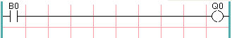
The input on the left, a normal open contact is connected to the output on the right Q0. Now imagine a voltage gets applied to the leftmost end, as soon as the B0 turns true (e.g. the input is activated, or the user pushed the NO contact), the voltage reaches the right part Q0. As a consequence, the Q0 output will turn from 0 to 1.
2. Classic Ladder
2.1. Introduction
Classic Ladder is a free implementation of a ladder interpreter, released under the LGPL. It has been written by Marc Le Douarain.
He describes the beginning of the project on his website Original project homepage:
 “I decided to program a ladder language only for test purposes at the
start, in February 2001. It was planned, that I would have to
participate to a new product after leaving the enterprise in which I
was working at that time. And I was thinking that to have a ladder
language in those products could be a nice option to considerate. And
so I started to code the first lines for calculating a rung with
minimal elements and displaying dynamically it under Gtk, to see if my
first idea to realize all this works.
 And as quickly I've found that it advanced quite well, I've continued
with more complex elements : timer, multiples rungs, etc...
 Voila, here is this work... and more : I've continued to add features
since then.”
Classic Ladder has been adapted to work with EMC2’s HAL, and is currently being distributed along with EMC2. If there are issues/problems/bugs please report them to the Enhanced Machine Controller project.
2.2. Ladder Concepts
Classic Ladder is a type of programming language originally implemented on industrial PLC’s (it’s called Ladder Programming). It is based on the concept of relay contacts and coils, and can be used to construct logic checks and functions in a manner that is familiar to many systems integrators. It is important to know how ladder programs are evaluated when running:
It seems natural that each line would be evaluated left to right then the next line down etc-but it doesn’t work this way. ALL the inputs are read, ALL the logic is figured out, then ALL the outputs are set. This can presents a problem in certain circumstance if the output of one line feeds the input of another. Another gotcha with ladder programming is the "Last One Wins" rule. If you have the same output in different locations of your ladder the state of the last one will be what the output is set to.
Classic Ladder version 7.124 has been adapted for EMC 2.3 This document describes that version.
2.3. Languages
The most common language used when working with Classic Ladder is ladder. Classic Ladder also supports Sequential Function Chart (Grafcet).
2.4. Components
There are 2 components to Classic Ladder.
-
The real time module classicladder_rt
-
The user space module (including a GUI) classicladder
2.4.1. Files
Typically classic ladder components are placed in the custom.hal file if your working from a Stepconf generated configuration. These must not be placed in the custom_postgui.hal file or the Ladder Editor menu will be grayed out.
Ladder files (.clp) must not contain any blank spaces in the name.
2.4.2. Realtime Module
Loading the Classic Ladder real time module (classicladder_rt) is possible from a hal file, or directly using a halcmd instruction. The first line loads real time the Classic Ladder module. The second line adds the function classicladder.0.refresh to the servo thread. This line makes Classic Ladder update at the servo thread rate.
loadrt classicladder_rt +
addf classicladder.0.refresh servo-thread
The speed of the thread that Classic Ladder is running in directly effects the responsiveness to inputs and outputs. If you can turn a switch on and off faster than Classic Ladder can notice it then you may need to speed up the thread. The fastest that Classic Ladder can update the rungs is one millisecond. You can put it in a faster thread but it will not update any faster. If you put it in a slower then one microsecond thread then Classic Ladder will update the rungs slower. The current scan time will be displayed on the section display, it is rounded to microseconds. If the scan time is longer than one millisecond you may want to shorten the ladder or put it in a slower thread.
2.4.3. Variables
It is possible to configure the number of each type of ladder object while loading the Classic Ladder real time module. If you do not configure the number of ladder objects Classic Ladder will use the default values.
Objects of most interest are numPhysInputs, numPhysOutputs, numS32in, and numS32out.
Changing these numbers will change the number of HAL bit pins available. numPhysInputs and numPhysOutputs control how many HAL bit (on/off) pins are available. numS32in and numS32out control how many HAL signed integers (+- integer range) pins are available.
For example (you don’t need all of these to change just a few):
 loadrt classicladder_rt numRungs=12 numBits=100 numWords=10
numTimers=10 numMonostables=10 numCounters=10 numPhysInputs=10
numPhysOutputs=10 numArithmExpr=100 numSections=4 numSymbols=200
numS32in=5 numS32out=5
To load the default number of objects:
loadrt classicladder_rt
2.5. Loading the Classic Ladder user module
Classic Ladder hal commands must executed before the GUI loads or the menu item Ladder Editor will not function. If you used the Stepper Config Wizard place any Classic Ladder hal commands in the custom.hal file.
To load the user module:
loadusr classicladder
To load a ladder file:
loadusr classicladder myladder.clp
Classic Ladder Loading Options
-
-- nogui (loads with out the ladder editor) normally used after debugging is finished.
-
`--`modbus_port=port (loads the modbus port number)
-
-- modmaster (initializes MODBUS master) should load the ladder program at the same time or the TCP is default port.
-
`--`modslave (initializes MODBUS slave) only TCP
To use Classic Ladder with HAL without EMC. The -w tells HAL not to close down the HAL environment until Classic Ladder is finished.
loadusr -w classicladder
If you first load ladder program with the -- nogui option then load Classic Ladder again with no options the GUI will display the last loaded ladder program.
In AXIS you can load the GUI from File/Ladder Editor…
2.6. Classic Ladder GUI
If you load Classic Ladder with the GUI it will display two windows: section display, and section manager.
2.6.1. Sections Manager
When you first start up Classic Ladder you get an empty Sections Manager window.
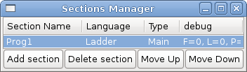
This window allows you to name, create or delete sections and choose what language that section uses. This is also how you name a subroutine for call coils.
2.6.2. Section Display
When you first start up Classic Ladder you get an empty Section Display window.
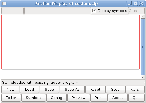
Most of the buttons are self explanatory:
The Vars button is for looking at variables, toggle it to display one, the other, both, then none of the windows.
The Config button is used for modbus and shows the max number of ladder elements that was loaded with the real time module.
The Symbols button will display an editable list of symbols for the variables (hint you can name the inputs, outputs, coils etc).
The Quit button will shut down the user program meaning Modbus and the display- the real time ladder program will still run in the back ground.
The check box at the top right allows you to select whether variable names or symbol names are displayed
You might notice that there is a line under the ladder program display that reads "Project failed to load…" That is the status bar that gives you info about elements of the ladder program that you click on in the display window. This status line will now display HAL signal names for variables %I, %Q and the first %W (in an equation) You might see some funny labels, such as (103) in the rungs. This is displayed (on purpose) because of an old bug- when erasing elements older versions sometimes didn’t erase the object with the right code. You might have noticed that the long horizontal connection button sometimes didn’t work in the older versions. This was because it looked for the free code but found something else. The number in the brackets is the unrecognized code. The ladder program will still work properly, to fix it erase the codes with the editor and save the program.
2.6.3. The Variable Windows
This are two variable windows: bool and signed integer. the vars button is in the section display window, toggle the Vars button to display one, the other, both, then none of the windows.
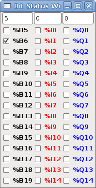
The Bool window displays some of all the bool (on/off) variable data . Notice all variable start with the % sign. The %I variable represents HAL input bit pins. The %Q represents the relay coil and HAL output bit pins. The %B represents an internal relay coil or internal contact The three edit areas at the top allow you to select what 15 variable will be displayed in each column. For instance if there were 30 %B variable and you entered 5 at the top of the column, variable %B5 to %B19 would be displayed. The check boxes allow you to set and unset %B variables manually as long as the ladder program isn’t setting them as outputs. Any Bits that are set as outputs by the program when Classic Ladder is running can not be changed and will be displayed as checked if on and unchecked if off.
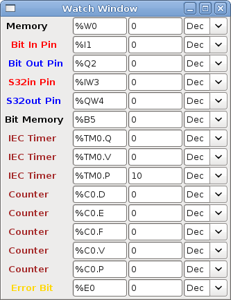
The Watch Window displays variable status. The edit box beside it is the number stored in the variable and the drop-down box beside that allow you to choose whether the number to be displayed in hex, decimal or binary. If there are symbol names defined in the symbols window for the word variables showing and the display symbols checkbox is checked the the section display window, symbol names will be displayed. To change the variable displayed type the variable number eg. %W2 (if display symbols check box is not checked) or symbol name (if the display symbols checkbox is checked) over an existing variable number/name and press the Enter Key.
2.6.4. Symbol Window
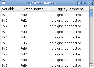
This is a list of symbol names to use instead of variable names to be displayed in the section window when the display symbols check box is checked. You add the variable name (remember the % symbol and capital letters), symbol name . If the variable can have a HAL signal connected to it (%I, %Q, and %W-if you have loaded s32 pin with the real time module) then the comment section will show the current HAL signal name or lack there of. symbol names should be kept short to display better. keep in mind that you can display the longer HAL signal name of %I, %Q and %W variable by clicking on them in the section window. Between the two on should be able to keep track of what the ladder program is connected to!
2.6.5. The Editor window
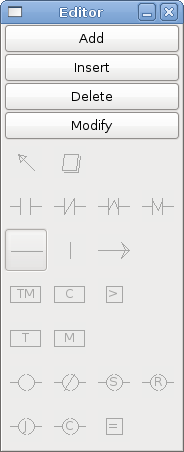
Starting from the top left image:
-
Object Selector, Eraser
-
N.O. Input, N.C. Input, Rising Edge Input , Falling Edge Input
-
Horizontal Connection, Vertical Connection , Long Horizontal Connection
-
Timer IEC Block, Counter Block, Compare Variable
-
Old Timer Block, Old Monostable Block (These have been replaced by the IEC Timer)
-
COILS - N.O. Output, N.C. Output, Set Output, Reset Output
-
Jump Coil, Call Coil, Variable Assignment
A short description of each of the buttons:
-
The SELECTOR ARROW button allows you to select existing objects and modify the information.
-
The ERASER erases an object.
-
The N.O. CONTACT is a normally open contact. It can be an external HAL-pin (%I) input contact, an internal-bit coil (%B) contact or a external coil (%Q) contact. The Hal-pin input contact is closed when the HAL-pin is true. The coil contacts are closed when the corresponding coil is active (%Q2 contact closes when %Q2 coil is active).
-
The N.C. CONTACT is a normally closed contact. It is the same as the n.o. contact except that the contact is open when the hal-pin is true or the coil is active.
-
The RISING-EDGE CONTACT is a contact that is closed when the HAL-pin goes from False to true, or the coil from not-active to active.
-
The FALLING-EDGE CONTACT is a contact that is closed when the HAL-pin goes from true to false or the coil from active to not.
-
The HORIZONTAL CONNECTION connects the signal to objects horizontally.
-
The VERTICAL CONNECTION connects the signal to objects vertically.
-
The HORIZONTAL-RUNNING CONNECTION is a quick way to connect a long run of signal wire horizontally.
-
The IEC TIMER replaces the TIMER and the MONSTABLE.
-
The TIMER is a Timer Module.
-
The MONOSTABLE is monostable module (one-shot)
-
The COUNTER is a counter module.
-
The COMPARE button allows you to compare variable to values or other variables. (eg %W1⇐5 or %W1=%W2) Compare cannot be placed in the right most side of the section display.
-
The VARIABLE ASSIGNMENT button allows you to assign values to variables. (eg %W2=7 or %W1=%W2) ASSIGNMENT functions can only be placed at the right most side of the section display.
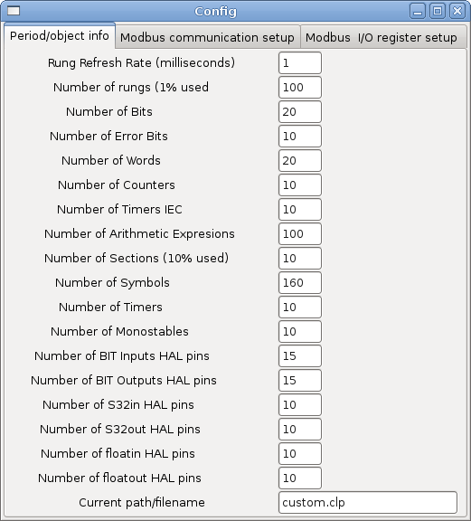
2.7. Ladder objects
2.7.1. CONTACTS
Represent switches or relay contacts. They are controlled by the variable letter and number assigned to them.
The variable letter can be B, I, or Q and the number can be up to a three digit number eg. %I2, %Q3, or %B123. Variable I is controlled by a Hal input pin with a corresponding number . Variable B is for internal contacts, controlled by a B coil with a corresponding number. Variable Q is controlled by a Q coil with a corresponding number. (like a relay with multiple contacts). Eg. if HAL pin classicladder.0.in-00 is true then %I0 N.O. contact would be on (closed, true, whatever you like to call it). If %B7 coil is energized (on, true, etc) then %B7 N.O. contact would be on. If %Q1 coil is energized then %Q1 N.O. contact would be on (and HAL pin classicladder.0.out-01 would be true.)
-
N.O. CONTACT
(Normally Open)
When the variable is false the switch is off.
-
N.C. CONTACT
(Normally
Closed) When the variable is false the switch is on.
-
RISING EDGE CONTACT - When the variable changes from false to true, the switch is PULSED on.
-
FALLING EDGE CONTACT - When the variable changes from true to false, the switch is PULSED on.
2.7.2. IEC TIMERS
Represent new count down timers! IEC Timers replace Timers and Monostables.
IEC Timers have 2 contacts.
-
I = input
-
Q = output
There are three modes - TON, TOF, TP.
-
TON : When timer input is true countdown begins and continues as long as input remains true. After countdown is done and as long as timer input is still true the output will be true.
-
TOF : When timer input is true, sets output true. When the input is false the timer counts down then sets output false.
-
TP : When timer input is pulsed true or held true timer sets output true till timer counts down. (one-shot)
The time intervals can be set in multiples of 100ms, seconds, or minutes.
There are also Variables for IEC timers that can be read and/or written to in compare or operate blocks.
-
%TMxxx.Q timer done (Boolean, read write)
-
%TMxxx.P timer preset (read write)
-
%TMxxx.V timer value (read write)
2.7.3. TIMERS
Represent count down timers. This is deprecated and replaced by IEC Timers.
Timers have 4 contacts.
-
E = enable (input) - starts timer when true, resets when goes false
-
C = control (input) - must be on for the timer to run (usually connect to E)
-
D = done (output) - true when timer times out and as long as E remains true
-
R = running (output) - true when timer is running
The timer base can be multiples of milliseconds, seconds, or minutes.
There are also Variables for timers that can be read and/or written to in compare or operate blocks.
-
%Txx.R : Timer xx running (Boolean, read only)
-
%Txx.D : Timer xx done (Boolean, read only)
-
%Txx.V : Timer xx current value (integer, read only)
-
%Txx.P : Timer xx preset (integer, read or write)
2.7.4. MONOSTABLES
Represent are one-shot timers. This is deprecated and replaced by IEC Timers.
Monostables have 2 contacts I and R.
-
I (input) -input -will start the mono timer running.
-
R (output) -running -will be true while timer is running.
The I contact is rising edge sensitive meaning it starts the timer only when changing from false to true (or off to on). While the timer is running the I contact can change with no effect to the running timer. R will be true and stay true till the timer finishes counting to zero. The timer base can be multiples of milliseconds, seconds, or minutes.
There are also Variables for monostables that can be read and/or written to in compare or operate blocks.
-
%Mxx.R : Monostable xx running (Boolean, read only)
-
%Mxx.V : Monostable xx current value (integer, read only)
-
%Mxx.P : Monostable xx preset (integer, read or write)
2.7.5. COUNTERS
-
Represent up/down counters.
-
There are 7 contacts:
-
R (input) -reset -will reset the count to 0.
-
P (input) -preset -will set the count to the preset number assigned from the edit menu.
-
U (input) -up count -will add one to the count.
-
D (input) -down count -will subtract one from the count.
-
E (output) -under flow -will be true when the count rolls over from 0 to 9999.
-
D (output) -done -will be true when the count equals the preset.
-
F (output) -overflow -will be true when the count rolls over from 9999 to 0.
The up and down count contacts are edge sensitive meaning they only count when the contact changes from false to true (or off to on if you rather).
The range is 0 to 9999.
There are also Variables for counters that can be read and/or written to in compare or operate blocks.
-
%Cxx.D : Counter xx done (Boolean, read only)
-
%Cxx.E : Counter xx empty overflow (Boolean, read only)
-
%Cxx.F : Counter xx full overflow (Boolean, read only)
-
%Cxx.V : Counter xx current value (integer, read or write)
-
%Cxx.P : Counter xx preset (integer, read or write)
2.7.6. COMPARE
For arithmetic comparison. Is variable %XXX = to this number (or evaluated number)
The compare block will be true when comparison is true. you can use most math symbols:
-
+, - ,* , /, = (standard math symbols)
-
< (less than), > (greater than), ⇐ (less or equal), >= (greater or equal), <> (not equal)
-
(, ) grouping
-
^ (exponent),% (modulus),& (and),| (or),. -
-
ABS (absolute), MOY (french for average) ,AVG (average)
For example ABS(%W2)=1, MOY(%W1,%W2)<3.
No spaces are allowed in the comparison equation. For example %C0.V>%C0.P is a valid comparison expression while %C0.V > %CO.P is not a valid expression.
There is a list of Variables down the page that can be used for reading writing to ladder objects. When a new compare block is opened be sure and delete the # symbol when you enter a compare.
To find out if word variable #1 is less than 2 times the current value of counter #0 the syntax would be:
%W1<2*%C0.V
To find out if S32in bit 2 is equal to 10 the syntax would be:
%IW2=10
Note: Compare uses the arithmetic equals not the double equals that programmers are use to.
2.7.7. VARIABLE ASSIGNMENT
For variable assignment. eg assign this number (or evaluated number) to this variable %xxx there are two math functions MINI and MAXI that check a variable for maximum (0x80000000) and minimum values (0x07FFFFFFF) (think signed values) and keeps them from going beyond.
When a new variable assignment block is opened be sure and delete the # symbol when you enter an assignment.
To assign a value of 10 to the timer preset of IEC Timer 0 the syntax would be:
%TM0.P=10
To assign the value of 12 to S32out bit 3 the syntax would be:
%QW3=12
The following figure shows an Assignment and a Comparison Example. %QW0 is a S32out bit and %IW0 is a S32in bit. In this case the HAL pin classicladder.0.s32out-00 will be set to a value of 5 and when the HAL pin classicladder.0.s32in-00 is 0 the HAL pin classicladder.0.out-00 will be set to True.
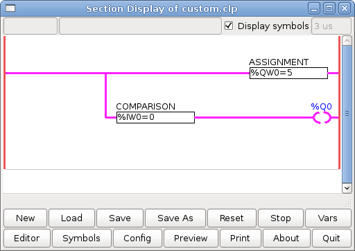
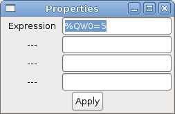
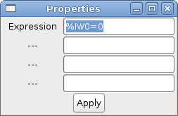
2.7.8. COILS
Coils represent relay coils. They are controlled by the variable letter and number assigned to them.
The variable letter can be B or Q and the number can be up to a three digit number eg. %Q3, or %B123. Q coils control HAL out pins. eg if &Q15 is energized then HAL pin classicladder.0.out-15 will be true. B coils are internal coils used to control program flow.
-
N.O. COIL -(a relay coil.) When coil is energized it’s N.O. contact will be closed (on, true, etc)
-
N.C. COIL -(a relay coil that inverses its contacts.) When coil is energized it"s N.O. contact will be open (off, false, etc)
-
SET COIL -(a relay coil with latching contacts) When coil is energized it’s N.O. contact will be latched closed.
-
RESET COIL -(a relay coil with latching contacts) When coil is energized It’s N.0. contact will be latched open.
-
JUMP COIL -(a "goto" coil) when coil is energized ladder program jumps to a rung (in the CURRENT section) -jump points are designated by a rung label. (Add rung labels in the section display, top left label box)
-
CALL COIL -(a "gosub" coil) when coil is energized program jumps to a subroutine section designated by a subroutine number -subroutines are designated SR0 to SR9 (designate them in the section manager)
WARNING if you use a N.C. contact with a N.C. coil the logic will work (when the coil is energized the contact will be closed) but that is really hard to follow!
JUMP COIL
A JUMP COIL is used to JUMP to another section-like a goto in BASIC programming language.
If you look at the top left of the sections display window you will see a small label box and a longer comment box beside it. Now go to Editor→Modify then go back to the little box, type in a name.
Go ahead and add a comment in the comment section. This label name is the name of this rung only and is used by the JUMP COIL to identify where to go.
When placing a JUMP COIL add it in the right most position and change the label to the rung you want to JUMP to.
CALL COIL
A CALL COIL is used to go to a subroutine section then return-like a gosub in BASIC programming language.
If you go to the sections manager window hit the add section button. You can name this section, select what language it will use (ladder or sequential), and select what type (main or subroutine).
Select a subroutine number (SR0 for example). An empty section will be displayed and you can build your subroutine.
When you’ve done that, go back to the section manager and click on the your main section (default name prog1).
Now you can add a CALL COIL to your program. CALL COILs are to be placed at the right most position in the rung.
Remember to change the label to the subroutine number you choose before.
2.8. Classic Ladder Variables
These Variables are used in COMPARE or OPERATE to get information about, or change specs of, ladder objects Such as changing a counter preset, or seeing if the a timer is done running.
List of variables :
-
%Bxxx : Bit memory xxx (Boolean)
-
%Wxxx : Word memory xxx (32 bits signed integer)
-
%IWxxx : Word memory xxx (S32 in pin)
-
%QWxxx : Word memory xxx (S32 out pin)
-
%IFxx : Word memory xx (Float in pin) (converted to S32 in Classic Ladder)
-
%QFxx : Word memory xx (Float out pin) (converted to S32 in Classic Ladder)
-
%Txx.R : Timer xx running (Boolean, user read only)
-
%Txx.D : Timer xx done (Boolean, user read only)
-
%Txx.V : Timer xx current value (integer, user read only)
-
%Txx.P : Timer xx preset (integer)
-
%TMxxx.Q : Timer xxx done (Boolean, read write)
-
%TMxxx.P : Timer xxx preset (integer, read write)
-
%TMxxx.V : Timer xxx value (integer, read write)
-
%Mxx.R : Monostable xx running (Boolean)
-
%Mxx.V : Monostable xx current value (integer, user read only)
-
%Mxx.P : Monostable xx preset (integer)
-
%Cxx.D : Counter xx done (Boolean, user read only)
-
%Cxx.E : Counter xx empty overflow (Boolean, user read only)
-
%Cxx.F : Counter xx full overflow (Boolean, user read only)
-
%Cxx.V : Counter xx current value (integer)
-
%Cxx.P : Counter xx preset (integer)
-
%Ixxx : Physical input xxx (Boolean) - HAL input bit -
-
%Qxxx : Physical output xxx (Boolean) - HAL output bit -
-
%Xxxx : Activity of step xxx (sequential language)
-
%Xxxx.V : Time of activity in seconds of step xxx (sequential language)
-
%Exx : Errors (Boolean, read write(will be overwritten))
-
Indexed or vectored variables These are variables indexed by another variable. Some might call this vectored variables. Example: %W0[%W4] ⇒ if %W4 equals 23 it corresponds to %W23
2.9. GRAFCET Programming
-
WARNING -These is probably the least used/known about feature of Classic Ladder. Sequential programming is used to make sure a series of ladder events always happen in a prescribed order. Sequential programs do not work alone-there is always a ladder program as well that controls the variables. Here are the basic rules governing sequential programs:
-
Rule 1 : Initial situation - The initial situation is characterized by the initial steps which are by definition in the active state at the beginning of the operation.There shall be at least one initial step.
-
Rule 2 : R2, Clearing of a transition - A transition is either enabled or disabled. It is said to be enabled when all immediately preceding steps linked to its corresponding transition symbol are active, otherwise it is disabled. A transition cannot be cleared unless: it is enabled, and its associated transition condition is true.
-
Rule 3 : R3, Evolution of active steps - The clearing of a transition simultaneously leads to the active state of the immediately following step(s) and to the inactive state of the immediately preceding step(s).
-
Rule 4 : R4, Simultaneous clearing of transitions - All simultaneous cleared transitions are simultaneously cleared.
-
Rule 5 : R5, Simultaneous activation and deactivation of a step - If during operation, a step is simultaneously activated and deactivated, priority is given to the activation.
-
This is the SEQUENTIAL editor window Starting from the top left image: Selector arrow , Eraser Ordinary step , Initial (Starting) step Transition , Step and Transition Transition Link-Downside , Transition Link-Upside Pass-through Link-Downside , Pass-through Link-Upside Jump Link Comment Box [show sequential program]
-
ORDINARY STEP-has a unique number for each one
-
STARTING STEP-a sequential program must have one. This is where the program will start.
-
TRANSITION-This shows the variable that must be true for control to pass through to the next step.
-
STEP AND TRANSITION -Combined for convenience
-
TRANSITION LINK-DOWNSIDE-splits the logic flow to one of two possible lines based on which of the next steps is true first (Think OR logic)
-
TRANSITION LINK=UPSIDE-combines two (OR) logic lines back in to one
-
PASS-THROUGH LINK-DOWNSIDE-splits the logic flow to two lines that BOTH must be true to continue (Think AND logic)
-
PASS-THROUGH LINK-UPSIDE-combines two concurrent (AND logic) logic lines back together
-
JUMP LINK-connects steps that are not underneath each other such as connecting the last step to the first
-
COMMENT BOX used to add comments
To use links you must have steps already placed , select the type of link , then select the two steps or transactions one at a time- It takes practice!
With sequential programming: The variable %Xxxx (eg. %X5) is used to see if a step is active. The variable %Xxxx.V (eg. %X5.V) is used to see how long the step has been active. The %X and %X.v variables are use in LADDER logic. The variables assigned to the transitions (eg. %B) control whether the logic will pass to the next step. After a step has become active the transition variable that caused it to become active has no control of it anymore. The last step has to JUMP LINK back (only to the beginning step?)
2.10. Modbus
Things to consider:
-
Modbus is a userspace program so it might have latency issues on a heavily laden computer.
-
Modbus is not really suited to Hard real time events such as position control of motors or to control E-stop.
-
The Classic Ladder GUI must be running for Modbus to be running.
-
Modbus is not fully finished so it does not do all modbus functions.
To get MODBUS to initialize you must specify that when loading the Classic Ladder userspace program eg. loadusr -w classicladder -- modmaster myprogram.clp (assuming myprogram.clp is present -w makes HAL wait till you close Classic Ladder before closing realtime session) my idea behind this is to get a working modbus solution out there then we can decide how it should be done in the best way. As it stands now Classic Ladder also loads a TCP modbus slave (if you add -- modserver on command line) - I have not tested this nor have I tested the TCP modbus master. I have done some testing with the serial port and had to add some functions to get it to talk to my VFD -but it does work. Modbus function 1,2,3,4,5,6,8,15,16 (read coils,read inputs, read holding registers, read input registers, write single coils, write single register, echo test, write multiple coils, write multiply registers) are currently available. If you do not specify a -- modmaster when loading the Classic Ladder user program this (next) page will not be displayed.
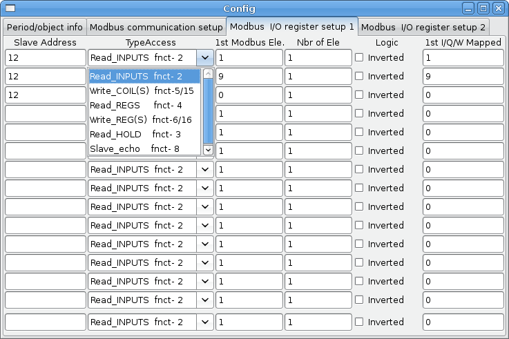
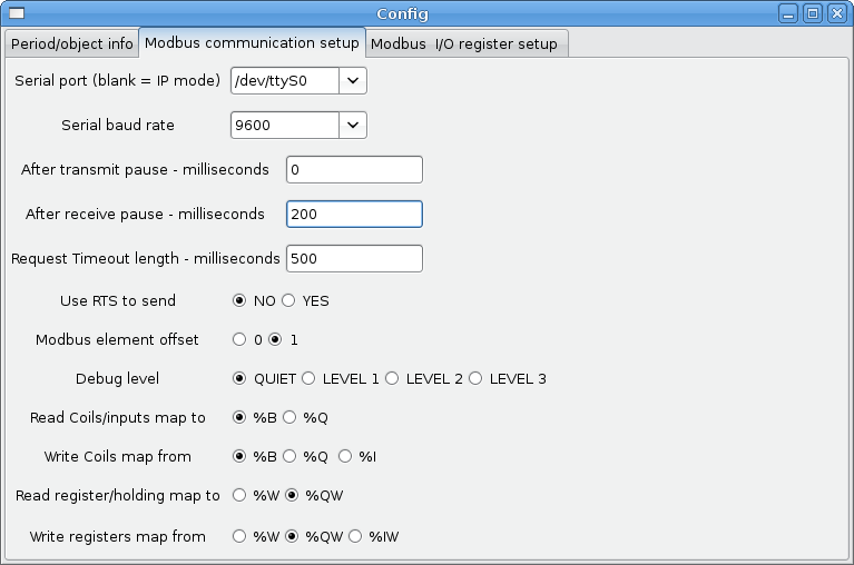
- SERIAL PORT
-
-
For IP blank. For serial the location/name of serial driver eg. /dev/ttyS0 ( or /dev/ttyUSB0 for a USB to serial converter )
-
- SERIAL SPEED
-
-
Should be set to speed the slave is set for - 300, 600, 1200, 2400, 4800, 9600, 19200, 38400, 57600, 115200 are supported.
-
- PAUSE AFTER TRANSMIT
-
-
Pause (milliseconds) after transmit and before receiving answer -some devices need more time (eg usb-serial converters)
-
- PAUSE INTER-FRAME
-
-
Pause (milliseconds) after receiving answer from slave- this sets the duty cycle of requests (it’s a pause for EACH request)
-
- REQUEST TIMEOUT LENGTH
-
-
Length (milliseconds) of time before we decide that the slave didn’t answer.
-
- MODBUS ELEMENT OFFSET
-
-
used to offset the element numbers by 1 (for manufacturers numbering differences)
-
- DEBUG LEVEL
-
-
Set this to 0-3 (0 to stop printing debug info besides no-response errors).
-
- READ COILS/INPUTS MAP TO
-
-
Select what variables that read coils/inputs will update. (B or Q)
-
- WRITE COILS MAP TO
-
-
Select what variables that write coils will updated.from (B,Q,or I)
-
- READ REGISTERS/HOLDING
-
-
Select what variables that read registers will update. (W or QW)
-
- WRITE REGISTERS MAP TO
-
-
Select what variables that read registers will updated from. (W, QW, or IW)
-
- SLAVE ADDRESS
-
-
For serial the slaves ID number usually settable on the slave device (usually 1-256) For IP the slave IP address plus optionally the port number.
-
- TYPE ACCESS
-
-
This selects the MODBUS function code to send to the slave (eg what type of request)
-
- Coils/inputs
-
are read/written to I, B, or Q variables (user selects)
- registers
-
and holding registers map to W, IW, or QW variables (usr selects)
- 1st MODBUS ELEMENT
-
-
The address (or register number) of the first element in a group. (remember to set MODBUS ELEMENT OFFSET properly)
-
- NUMBER OF ELEMENTS
-
-
The number of elements in this group
-
- LOGIC
-
-
You can invert the logic here
-
- 1st%I%Q IQ WQ MAPPED
-
-
This is the starting number of %B, %I, %Q, %W, %IW, or %QW variables that are mapped onto/from the modbus element group (starting at the first modbus element number).
-
In the example above: Port number- for my computer /dev/ttyS0 was my serial port
The serial speed is set to 9600 baud.
Slave address is set to 12 ( on my VFD I can set this from 1-31, meaning I can talk to 31 VFDs maximum on one system)
The first line is set up for 8 input bits starting at the first register number (register 1) so register numbers 1-8 and maps them on to Classic Ladder’s %B variables starting at %B1 ending at %B8.
The second line is set for 2 output bits starting at the ninth register number (register 9) so register numbers 9-10 and maps them on to Classic Ladder’s %Q variables starting at %Q9 ending at %Q10.
The third line is set to write 2 registers (16 bit each) starting at the 0th register number (register 0) so register numbers 0-1 and maps them on to Classic Ladder’s %W variables starting at %W0 ending at %W1
It’s easy to make an off-by-one error as sometimes the modbus elements are referenced starting at one rather then 0 (actually by the standard that is the way it’s supposed to be!) You can use the modbus element offset radio button to help with this.
The documents for your modbus slave device will tell you how the registers are set up- there is no standard way.
The SERIAL PORT, PORT SPEED, PAUSE, and DEBUG level are editable for changes (when you close the config window values are applied though Radio buttons apply immediately)
To use the echo function select the echo function and add the slave number you wish to test. You don’t need to specify any variables.
The number 257 will be sent to the slave number you specified and the slave should send it back. you will need to have Classic Ladder running in a terminal to see the message.
2.10.1. MODBUS Settings
Serial:
-
Classic Ladder uses RTU protocol (not ASCII)
-
8 data bits, No parity is used, and 1 stop bit is also known as 8-N-1
-
Baud rate must be the same for slave and master. Classic Ladder can only have one baud rate so all the slaves must be set to the same rate.
-
Pause inter frame is the time to pause after receiving an answer.
-
MODBUS_TIME_AFTER_TRANSMIT is the length of pause after sending a request and before receiving an answer (this apparently helps with USB converters which are slow)
2.10.2. MODBUS Info
-
Classic Ladder can use distributed inputs/outputs on modules using the modbus protocol ("master": polling slaves).
-
The slaves and theirs I/O can be configured in the config window.
-
2 exclusive modes are available : ethernet using Modbus/TCP and serial using Modbus/RTU.
-
No parity is used.
-
If no port name for serial is set, TCP/IP mode will be used…
-
The slave address is the slave address (Modbus/RTU) or the IP address.
-
The IP address can be followed per the port number to use (xx.xx.xx.xx:pppp) else the port 9502 will be used per default.
-
2 products have been used for tests: a Modbus/TCP one (Adam-6051, http://www.advantech.com) and a serial Modbus/RTU one (http://www.ipac.ws)
-
See examples: adam-6051 and modbus_rtu_serial.
-
Web links: http://www.modbus.org and this interesting one: http://www.iatips.com/modbus.html
-
MODBUS TCP SERVER INCLUDED
-
Classic Ladder has a Modbus/TCP server integrated. Default port is
-
(the previous standard 502 requires that the application must be launched with root privileges).
-
-
List of Modbus functions code supported are: 1, 2, 3, 4, 5, 6, 15 and 16.
-
Modbus bits and words correspondence table is actually not parametric and correspond directly to the %B and %W variables.
Info on modbus protocol are available here:
2.10.3. Communication Errors
If there is a communication error, a warning window will pop up (if the GUI is running) and %E0 will be true. Modbus will continue to try and communicate. The %E0 could be used to make a decision based on the error. A timer could be used to stop the machine if timed out etc.
2.10.4. MODBUS Bugs
-
In compare blocks the function %W=ABS(%W1-%W2) is accepted but does not compute properly. only %W0=ABS(%W1) is currently legal
-
When loading a ladder program it will load Modbus info but will not tell Classic Ladder to initialize Modbus. You must initialize Modbus when you first load the GUI by adding `--`modmaster
-
If the section manager is placed on top of the section display, across the scroll bar and exit is clicked the user program crashes.
-
When using -- modmaster you must load the ladder program at the same time or else only TCP will work.
-
reading/writing multiply registers in Modbus has checksum errors
2.11. Setting up Classic Ladder
In this section we will cover the steps needed to add Classic Ladder to a Stepconf Wizard generated config. On the advanced Configuration Options page of Stepconf Wizard check off "Include Classic Ladder PLC"
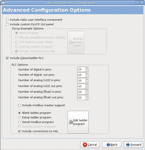
2.11.1. Add the Modules
If you used the Stepconf Wizard to add Classic Ladder you can skip this step.
To manually add Classic Ladder you must first add the modules. This is done by adding a couple of lines to the custom.hal file.
This line loads the real time module:
loadrt classicladder_rt
This line adds the Classic Ladder function to the servo thread:
addf classicladder.0.refresh servo-thread
2.11.2. Adding Ladder Logic
Now start up your config and select File/Ladder Editor… to open up the Classic Ladder GUI. You should see a blank Section Display and Sections Manager window as shown above. In the Section Display window open the Editor. In the Editor window select Modify. Now a Properties window pops up and the Section Display shows a grid. The grid is one rung of ladder. The rung can contain branches. A simple rung has one input, a connector line and one output.
Now click on the N.O. Input in the Editor Window.
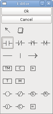
Now click in the upper left grid to place the N.O. Input into the ladder.
Repeat the above steps to add a N.O. Output to the upper right grid and use the Horizontal Connection to connect the two. It should look like the following. If not use the Eraser to remove unwanted sections.
Now click on the OK button in the Editor window. Now your Section Display should look like this.
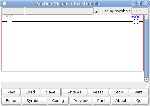
To save the new file select Save As and give it a name. The .clp extension will be added automatically. It should default to the running config directory as the place to save it.
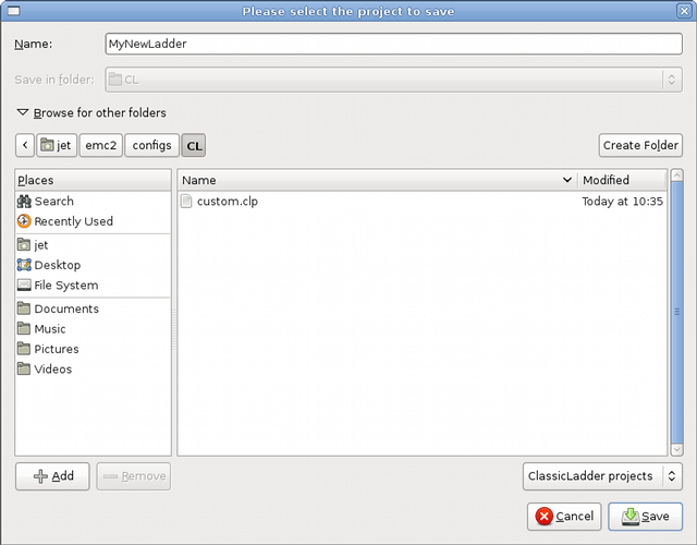
Again if you used the Stepconf Wizard to add Classic Ladder you can skip this step.
To manually add a ladder you need to add add a line to your custom.hal file that will load your ladder file. Close your EMC2 session and add this line to your custom.hal file.
loadusr -w classicladder `--`nogui MyLadder.clp
Now if you start up your EMC2 config your ladder program will be running as well. If you select File/Ladder Editor… the program you created will show up in the Section Display window.
2.12. Ladder Examples
2.12.1. Wrapping Counter
To have a counter that "wraps around" you have to use the preset pin and the reset pin. When you create the counter set the preset at the number you wish to reach before wrapping around to 0. The logic is if the counter value is over the preset then reset the counter and if the underflow is on then set the counter value to the preset value. As you can see in the example when the counter value is greater than the counter preset the counter reset is triggered and the value is now 0. The underflow output %Q2 will set the counter value at the preset when counting backwards.
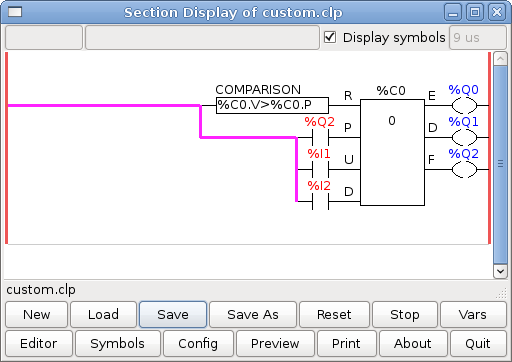
2.12.2. Reject Extra Pulses
This example shows you how to reject extra pulses from an input. Suppose the input pulse %I0 has an annoying habit of giving an extra pulse that spoils our logic. The TOF (Timer Off Delay) prevents the extra pulse from reaching our cleaned up output %Q0. How this works is when the timer gets an input the output of the timer is on for the duration of the time setting. Using a normally closed contact %TM0.Q the output of the timer blocks any further inputs from reaching our output until it times out.
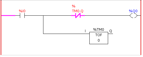
2.12.3. External E-Stop
The External E-Stop example is in the /config/classicladder/cl-estop folder. It uses a pyVCP panel to simulate the external components.
To interface an external E-Stop to EMC and have the external E-Stop work together with the internal E-Stop requires a couple of connections through ClassicLadder.
First we have to open the E-Stop loop in the main hal file by commenting out by adding the pound sign as shown or removing the following lines.
# net estop-out <= iocontrol.0.user-enable-out +
# net estop-out => iocontrol.0.emc-enable-in
Next we add ClassicLadder to our custom.hal file by adding these two lines:
loadrt classicladder_rt +
addf classicladder.0.refresh servo-thread
Next we run our config and build the ladder as shown here.
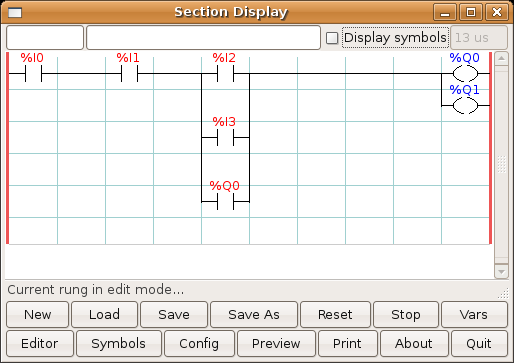
After building the ladder select Save As and save the ladder as estop.clp
Now add the following line to your custom.hal file.
# Load the ladder +
loadusr classicladder --nogui estop.clp
I/O assignments
-
%I0 = Input from the pyVCP panel simulated E-Stop (the checkbox)
-
%I1 = Input from EMC’s E-Stop
-
%I2 = Input from EMC’s E-Stop Reset Pulse
-
%I3 = Input from the pyVCP panel reset button
-
%Q0 = Ouput to EMC to enable
-
%Q1 = Output to external driver board enable pin (use a N/C output if your board had a disable pin)
Next we add the following lines to the custom_postgui.hal file
# E-Stop example using pyVCP buttons to simulate external components
# The pyVCP checkbutton simulates a normally closed external E-Stop +
net ext-estop classicladder.0.in-00 <= pyvcp.py-estop
# Request E-Stop Enable from EMC +
net estop-all-ok iocontrol.0.emc-enable-in <= classicladder.0.out-00
# Request E-Stop Enable from pyVCP or external source +
net ext-estop-reset classicladder.0.in-03 <= pyvcp.py-reset
# This line resets the E-Stop from EMC +
 net emc-reset-estop iocontrol.0.user-request-enable =>
classicladder.0.in-02
# This line enables EMC to unlatch the E-Stop in classicladder +
net emc-estop iocontrol.0.user-enable-out => classicladder.0.in-01
# This line turns on the green indicator when out of E-Stop +
net estop-all-ok => pyvcp.py-es-status
Next we add the following lines to the panel.xml file. Note you have to open it with the text editor not the default html viewer.
<pyvcp> +
<vbox> +
<label><text>"E-Stop Demo"</text></label> +
<led> +
<halpin>"py-es-status"</halpin> +
<size>50</size> +
<on_color>"green"</on_color> +
<off_color>"red"</off_color> +
</led> +
<checkbutton> +
<halpin>"py-estop"</halpin> +
<text>"E-Stop"</text> +
</checkbutton> +
</vbox> +
<button> +
<halpin>"py-reset"</halpin> +
<text>"Reset"</text> +
</button> +
</pyvcp>
Now start up your config and it should look like this.
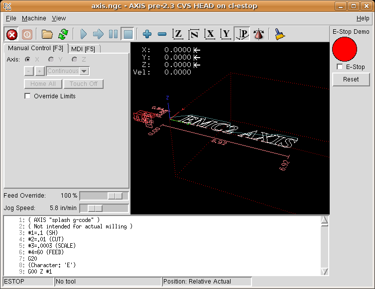
Note that in this example like in real life you must clear the remote E-Stop (simulated by the checkbox) before the AXIS E-Stop or the external Reset will put you in OFF mode. If the E-Stop in the AXIS screen was pressed you must press it again to clear it. You cannot reset from the external after you do an E-Stop in AXIS.
2.12.4. Timer/Operate Example
In this example we are using the Operate block to assign a value to the timer preset based on if an input is on or off.
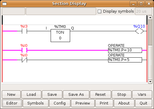
In this case %I0 is true so the timer preset value is 10. If %I0 was false the timer preset would be 5.
2.12.5. Tool Turret
-
This Example is not complete yet.
This is a program for one type of tool turret. The turret has a home switch at tool position 1 and another switch to tell you when the turret is in a lockable position. To keep track of the actual tool number one must count how many positions past home you are. We will use ClassicLadder’s counter block $CO.The counter is preset to 1 when RESET is true. The counter is increased by one on the rising edge of INDEX. We then COMPARE the counter value (%C0.V) to the tool number we want (in the example only checks for tool 1 and 2 are shown). We also OPERATE the counter value to a word variable (%W0) that (you can assume) is mapped on to a S32 out HAL pin so you can let some other HAL component know what the current tool number is. In the real world another S32 (in) pin would be used to get the requested tool number from EMC.You would have to load ClassicLadder’s real time module specifying that you want S32 in and out pins. See loading options above. [display turret sample]
2.12.6. Sequential Example
-
This Example is not complete yet.
This is a sequential program when the program is first started step one is active then when %B0 is true then steps 2 and 3 are then active and step one is inactive then when %B1 and/or %B2 are true, step 4 and/or 5 are active and step 2 and/or 3 are inactive Then when either %B3 OR %B4 are true, step 6 is true and steps 4 and 5 are inactive then when %B5 is true step 1 is active and step 6 is inactive and it all starts again As shown the sequence has been: %B0 was true making step 2 and 3 active then %B1 became true (and still is-see the pink line through %B1) making step 4 active and step 2 inactive step 3 is active and waiting for %B2 to be true step 4 is active and is waiting for %B3 to be true WOW that was quite a mouth full!! [display sequential program]
Hardware Examples
1. Second Parallel Port
When you add a second parallel port to your PCI bus you have to find out the address before you can use it with EMC.
To find the address of your parallel port card open a terminal window and type
lspci -v
You will see something similar to this as well as info on everything else on the PCI bus:
 0000:00:10.0 Communication controller: NetMos Technology PCI 1 port
parallel adapter (rev 01)  +
Subsystem: LSI Logic / Symbios Logic: Unknown device 0010  +
Flags: medium devsel, IRQ 11  +
I/O ports at a800 [size=8]  +
I/O ports at ac00 [size=8]  +
I/O ports at b000 [size=8]  +
I/O ports at b400 [size=8]  +
I/O ports at b800 [size=8]  +
I/O ports at bc00 [size=16]
In my case the address was the first one so I changed my .hal file from
loadrt hal_parport cfg=0x378
to
loadrt hal_parport cfg="0x378 0xa800 in"
Note the double quotes surrounding the addresses.
and then added the following lines so the parport will get read and written to.
addf parport.1.read base-thread  +
addf parport.1.write base-thread
After doing the above then run your config and verify that the parallel port got loaded in Machine/Show Hal Configuration window.
2. Spindle Control
2.1. 0-10v Spindle Speed
If your spindle is controlled by a VFD with a 0 to 10 volt signal and your using a DAC card like the m5i20 to output the control signal.
First you need to figure the scale of spindle speed to control signal. For this example the spindle top speed of 5000 RPM is equal to 10 volts. 10/5000=0.002 so our scale factor is 0.002
We have to add a scale component to the hal file to scale the motion.spindle-speed-out to the 0 to 10 needed by the VFD if your DAC card does not do scaling.
loadrt scale count=1
2.2. PWM Spindle Speed
If your spindle can be controlled by a PWM signal, use the pwmgen component to create the signal:
loadrt pwmgen output_type=0
This assumes that the spindle controller’s response to PWM is simple: 0% PWM gives 0RPM, 10% PWM gives 180 RPM, etc. If there is a minimum PWM required to get the spindle to turn, follow the example in the nist-lathe sample configuration to use a scale component.
2.3. Spindle Enable
If you need a spindle enable signal link your output pin to motion.spindle-on. To link these pins to a parallel port pin put something like the following in your .hal file making sure you pick the pin that is connected to your control device.
net spindle-enable motion.spindle-on => parport.0.pin-14-out
2.4. Spindle Direction
If you have direction control of your spindle the hal pins motion.spindle-forward and motion.spindle-reverse are controlled by M3 and M4. Spindle speed "Sn" must be set to a positive non zero value for M3/4 to turn on spindle motion.
To link these pins to a parallel port pin put something like the following in your .hal file making sure you pick the pin that is connected to your control device.
net spindle-fwd motion.spindle-forward => parport.0.pin-16-out
2.5. Spindle Soft Start
If you need to ramp your spindle speed command and your control does not have that feature it can be done in HAL. Basically you need to hijack the output of motion.spindle-speed-out and run it through a limit2 component with the scale set so it will ramp the rpm from motion.spindle-speed-out to your device that receives the rpm. The second part is to let EMC know when the spindle is at speed so motion can begin.
In the 0-10 volt example the line "net spindle-speed-scale motion.spindle-speed-out ⇒ scale.0.in" is changed as shown in the following example.
# load real time a limit2 and a near with names so it is easier to follow
# add the functions to a thread
# set the parameter for max velocity
# hijack the spindle speed out and send it to spindle ramp in
# the output of spindle ramp is sent to the scale in
# to know when to start the motion we send the near component
# the output from spindle-at-speed is sent to motion.spindle-at-speed
3. Spindle Feedback
3.1. Spindle Synchronized Motion
Spindle feedback is needed by EMC to perform any spindle coordinated motions like threading and constant surface speed. The StepConf Wizard can perform the connections for you if you select Encoder Phase A and Encoder Index as inputs.
Hardware assumptions:
-
An encoder is connected to the spindle and puts out 100 pulses per revolution on phase A
-
The encoder A phase is connected to the parallel port pin 10
-
The encoder index pulse is connected to the parallel port pin 11
Basic Steps to add the components and configure them:
loadrt encoder num_chan=1
3.2. Spindle At Speed
To enable EMC to wait for the spindle to be at speed before executing a series of moves you need to set motion.spindle-at-speed to true when the spindle is at the commanded speed. To do this you need spindle feedback from an encoder. Since the feedback and the commanded speed are not usually exactly the same you need to use the "near" component to say that the two numbers are close enough. The connections needed are from the spindle velocity command signal to near.n.in1 and from the spindle velocity from the encoder to near.n.in2. Then the near.n.out is connected to motion.spindle-at-speed. The near.n.scale needs to be set to say how close the two numbers must be before turning on the output. Depending on your setup you may need to adjust the scale to work with your hardware. The following is typical of the additions needed to your hal file to enable Spindle At Speed. If you already have near in your hal file then increase the count and adjust code to suit. Check to make sure the signal names are the same in your hal file.
loadrt near
addf near.0 servo-thread
net spindle-cmd near.0.in1
net spindle-velocity near.0.in2
net spindle-at-speed motion.spindle-at-speed <= near.0.out
setp near.0.scale 1.01
4. MPG Pendant
This example is to explain how to hook up the common MPG pendants found on the market place today. This example uses a MPG3 pendant and a C22 pendant interface card from CNC4PC connected to a second parallel port plugged into the PCI slot. This example gives you 3 axis with 3 step increments of 0.1, 0.01, 0.001
In your custom.hal file or other .hal file add the following making sure you don’t have mux4 or an encoder already in use. If you do just increase the counts and change the reference number. More information about mux4 and encoder can be found here [cha:HAL-Components] and here [sec:Encoder].
# Jog Pendant +
loadrt encoder num_chan=1 +
loadrt mux4 count=1 +
addf encoder.capture-position servo-thread +
addf encoder.update-counters base-thread +
addf mux4.0 servo-thread
# If your MPG outputs a quadture signal per click set x4 to 1  +
# If your MPG puts out 1 pulse per click set x4 to 0 +
setp encoder.0.x4-mode 0
# For velocity mode, set n to 1  +
 # In velocity mode the axis stops when dial is stopped even if that
means  +
# the commanded motion is not completed,  +
# For position mode (the default), set n to 0  +
# In position mode the axis will move exactly jog-scale  +
# units for each count, regardless of how long that might take,  +
# This must be set for each axis you want to behave other than default +
setp axis.N.jog-vel-mode n
setp mux4.0.in0 0.1 +
setp mux4.0.in1 0.01 +
setp mux4.0.in2 0.001 +
net scale1 mux4.0.sel0 <= parport.1.pin-09-in +
net scale2 mux4.0.sel1 <= parport.1.pin-10-in +
net pend-scale axis.0.jog-scale <= mux4.0.out +
net pend-scale axis.1.jog-scale +
net pend-scale axis.2.jog-scale +
net mpg-a encoder.0.phase-A <= parport.1.pin-02-in +
net mpg-b encoder.0.phase-B <= parport.1.pin-03-in +
net mpg-x axis.0.jog-enable <= parport.1.pin-04-in +
net mpg-y axis.1.jog-enable <= parport.1.pin-05-in +
net mpg-z axis.2.jog-enable <= parport.1.pin-06-in +
net pend-counts axis.0.jog-counts <= encoder.0.counts +
net pend-counts axis.1.jog-counts +
net pend-counts axis.2.jog-counts
5. GS2 Spindle
This example shows the connections needed to use an Automation Direct GS2 VFD to drive a spindle. The spindle speed and direction is controlled by EMC.
Using the GS2 component involves very little to set up. We start with a Stepconf Wizard generated config. Make sure the pins with "Spindle CW" and "Spindle PWM" are set to unused in the parallel port setup screen.
In the custom.hal file we place the following to connect EMC to the GS2 and have EMC control the drive.
# load the user space component for the Automation Direct GS2 VFD's +
loadusr -Wn spindle-vfd gs2_vfd -n spindle-vfd
# connect the spindle direction pin to the GS2 +
net gs2-fwd spindle-vfd.spindle-fwd <= motion.spindle-forward
# connect the spindle on pin to the GS2 +
net gs2-run spindle-vfd.spindle-on <= motion.spindle-on
# connect the GS2 at speed to the motion at speed +
net gs2-at-speed motion.spindle-at-speed <= spindle-vfd.at-speed
# connect the spindle RPM to the GS2 +
net gs2-RPM spindle-vfd.speed-command <= motion.spindle-speed-out
On the GS2 drive itself you need to set a couple of things before the modbus communications will work. Other parameters might need to be set based on your physical requirements but is beyond the scope of this manual. Refer to the GS2 manual that came with the drive for more information on parameters.
-
The communications switches must be set to RS-232C
-
The motor parameters must be set
-
P3.00 (Source of Operation Command) must be set to Operation determined by RS-485 interface 03 or 04
-
P4.00 (Source of Frequency Command) must be set to Frequency determined by RS232C/RS485 communication interface 05
-
P9.02 (Communication Protocol) must be set to Modbus RTU mode 8 data bits, no parity, 2 stop bits 03
A pyVCP panel based on this example is in the pyVCP Examples section of this manual.
Diagnostics :leveloffset: 1
Steppers
If what you get is not what you expect many times you just got some experience. Learning from the experience increases your understanding of the whole. Diagnosing problems is best done by divide and conquer. By this I mean if you can remove 1/2 of the variables from the equation each time you will find the problem the fastest. In the real world this is not always the case but a good place to start usually.
1. Common Problems
1.1. Stepper Moves One Step
The most common reason in a new installation for the stepper not to move is the step and direction signals are backwards. If you press the jog foward and backward key and the stepper moves one step each time in the same direction there is your sign.
1.2. No Steppers Move
Many drives have an enable pin or need a charge pump to enable the output.
1.3. Distance Not Correct
If you command the axis to move a specific distance and it does not move that distance then your scale is wrong.
2. Error Messages
2.1. Following Error
The concept of a following error is funny when talking about stepper motors. Since they are an open loop system, there is no position feedback to let you know if you actually are out of range. EMC calculates if it can keep up with the motion called for and if not then it gives a following error. Following errors usually are the result of one of the following on stepper systems.
-
FERROR to small
-
MIN_FERROR to small
-
MAX_VELOCITY to fast
-
MAX_ACCELERATION to fast
-
BASE_PERIOD set to long
-
Backlash added to an axis
Any of the above can cause the RT pulsing to not be able to keep up the requested step rate. This can happen if you didn’t run the latency test long enough to get a good number to plug into the Stepconf Wizard or if you set the Maximum Velocity or Maximum Acceleration too high.
If you added backlash you need to increase the STEPGEN_MAXACCEL up to double the MAX_ACCELERATION in the AXIS section of the INI file for each axis you added backlash to. EMC uses "extra acceleration" at a reversal to take up the backlash. Without backlash correction step generator acceleration can be just a few percent above the motion planner acceleration.
2.2. RTAPI Error
When you get this error:
RTAPI: ERROR: Unexpected realtime delay on task n
This error is generated by rtapi based on an indication from rtai that a deadline was missed. It is usually an indication that the BASE_PERIOD in the [EMCMOT] section of the ini file is set too low. You should run the Latency Test for an extended period of time to see if you have any delays that would cause this problem. If you used the Stepconf Wizard run it again and test the Base Period Jitter again and adjust the Base Period Maximum Jitter on the Basic Machine Information page. You might have to leave the test running for an extended period of time to find out if some hardware causes intermittent problems.
EMC2 tracks the number of CPU cycles between invocations of the real-time thread. If some element of your hardware is causing delays or your realtime threads are set too fast you will get this error.
|
Note
|
This error is only displayed once per session. If you had your BASE_PERIOD too low you could get hundreds of thousands of error messages per second if more than one was displayed. |
3. Testing
3.1. Step Timing
If you are seeing an axis ending up in the wrong location over multiple moves, it is likely that you do not have the correct direction hold times or step timing for your stepper drivers. Each direction change may be losing a step or more. If the motors are stalling, it is also possible you have either the MAX_ACCELERATION or MAX_VELOCITY set too high for that axis.
The following program will test the Z axis configuration for proper setup. Copy the program to your emc2/nc_files directory and name it TestZ.ngc or similar. Zero your machine with Z = 0.000 at the table top. Load and run the program. It will make 200 moves back and forth from 0.5 to 1". If you have a configuration issue, you will find that the final position will not end up 0.500" that the axis window is showing. To test another axis just replace the Z with your axis in the G0 lines.
( test program to see if Z axis loses position ) +
( msg, test 1 of Z axis configuration ) +
G20 #1000=100 ( loop 100 times ) +
( this loop has delays after moves ) +
( tests acc and velocity settings ) +
o100 while [#1000] +
G0 Z1.000 +
G4 P0.250 +
G0 Z0.500 +
G4 P0.250 +
#1000 = [#1000 - 1] +
o100 endwhile +
( msg, test 2 of Z axis configuration S to continue) +
M1 (stop here) +
#1000=100 ( loop 100 times ) +
( the next loop has no delays after moves ) +
 ( tests direction hold times on driver config and also max accel
setting ) +
o101 while [#1000]  +
G0 Z1.000 +
G0 Z0.500 +
#1000 = [#1000 - 1] +
o101 endwhile +
( msg, Done...Z should be exactly .5" above table ) +
M2
FAQ
1. Linux FAQ
These are some basic Linux commands and techniques for new to Linux users. More complete information can be found on the web or by using the man pages.
1.1. Automatic Login
When you install EMC2 with the Ubuntu LiveCD the default is to have to log in each time you turn the computer on. To enable automatic login go to System/Administration/Login Window. If it is a fresh install the Login Window might take a second or three to pop up. You will have to have your password that you used for the install to gain access to the Login Window Preferences window. In the Security tab check off Enable Automatic Login and pick a user name from the list (that would be you).
1.2. Automatic Startup
To have EMC start automatically with your config after turning on the computer go to System/Preferences/Sessions Startup Programs , add new. Navigate to your config and select the .ini file. When the file picker dialog closes add emc and a space in front of the path to your .ini file.
Example:
emc /home/mill/emc2/config/mill/mill.ini
1.3. Man Pages
Man pages are automatically generated manual pages in most cases. Man pages are usually available for most programs and commands in Linux.
To view a man page open up a terminal window by going to Applications, Accessories, Terminal. For example if you wanted to find out something about the find command in the terminal window type:
man find
Use the Page Up and Page Down keys to view the man page and the Q key to quit viewing.
1.4. List Modules
Sometimes when troubleshooting you need to get a list of modules that are loaded. In a terminal window type:
lsmod
If you want to send the output from lsmod to a text file in a terminal window type:
lsmod > mymod.txt
The resulting text file will be located in the home directory if you did not change directories when you opened up the terminal window and it will be named mymod.txt or what ever you named it.
1.5. Editing a Root File
When you open the file browser and you see the Owner of the file is root you must do extra steps to edit that file. Editing some root files can have bad results. Be careful when editing root files. You can open and view most root files normally but they will open in “read only” mode.
1.5.1. The Command Line Way
Open up Applications, Accessories, Terminal.
In the terminal window type
sudo gedit
Open the file with File, Open then edit
1.5.2. The GUI Way
-
Right click on the desktop and select Create Launcher
-
Type a name in like sudo edit
-
Type gksudo "gnome-open %u" as the command and save the launcher to your desktop
-
Drag a file onto your launcher to open and edit
1.5.3. Root Access
In Ubuntu you can become root by typing in "sudo -i" in a terminal window then typing in your password. You can really foul up things if you don’t know what your doing as root.
1.6. Terminal Commands
1.6.1. Working Directory
To find out the path to the present working directory in the terminal window type:
pwd
1.6.2. Changing Directories
To move up one level in the terminal window type:
cd ..
To move up two levels in the terminal window type:
cd ../..
To move down to the emc2/configs subdirectory in the terminal window type:
cd emc2/configs
1.6.3. Listing files in a directory
To view a list of all the files and subdirectories in the terminal window type:
dir
or
ls
1.6.4. Finding a File
The find command can be a bit confusing to a new Linux user. The basic syntax is:
find starting-directory parameters actions
For example to find all the .ini files in your emc2 directory you first need to use the pwd command to find out the directory. Open a new terminal window and type:
pwd
might return the following result
/home/joe
With this information put the command together like this:
find /home/joe/emc2 -name *.ini -print
The -name is the name of the file your looking for and the -print tells it to print out the result to the terminal window. The *.ini tells find to return all files that have the .ini extension.
To find all the files in the directory named and all the subdirectories under that add the -L option to the find command like this:
find -L /home/joe/emc2 -name *.ini -print
1.6.5. Searching for Text
grep -i -r 'text to search for' *
To find all the files that contain the text to search for in the current directory and all the subdirectories below the current while ignoring the case. The -i is for ignore case and the -r is for recursive (include all subdirectories in the search). The * is a wild card for search all files.
1.6.6. Bootup Messages
To view the bootup messages use "dmesg" from the command window. To save the bootup messages to a file use the redirection operator like this:
dmesg > bootmsg.txt
The contents of this file can be copied and pasted on line to share with people trying to help you diagnose your problem.
To clear the message buffer type this:
sudo dmesg -c
This can be useful to do just before you launch EMC to only show the infomation related to the start up of EMC.
1.7. Convenience Items
1.7.1. Terminal Launcher
If you want to add a terminal launcher to the panel bar on top of the screen you typically can right click on the panel at the top of the screen and select "Add to Panel". Select Custom Application Launcher and Add. Give it a name and put gnome-terminal in the command box.
1.8. Hardware Problems
1.8.1. Hardware Info
To find out what hardware is connected to your motherboard in a terminal window type:
lspci -v
1.8.2. Monitor Resolution
During installation Ubuntu attempts to detect the monitor settings. If this fails you are left with a generic monitor with a maximum resolution of 800x600.
Instructions for fixing this are located here:
Appendices
1. Glossary
A listing of terms and what they mean. Some terms have a general meaning and several additional meanings for users, installers, and developers.
- Acme Screw
-
A type of lead-screw that uses an acme thread form. Acme threads have somewhat lower friction and wear than simple triangular threads, but ball-screws are lower yet. Most manual machine tools use acme lead-screws.
- Axis
-
One of the computer control movable parts of the machine. For a typical vertical mill, the table is the X axis, the saddle is the Y axis, and the quill or knee is the Z axis. Additional linear axes parallel to X, Y, and Z are called U, V, and W respectively. Angular axes like rotary tables are referred to as A, B, and C.
- Axis
-
One of the Graphical User Interfaces available to users of EMC2. Features the modern use of menus and mouse buttons while automating and hiding some of the more traditional EMC2 controls. It is the only open-source interface that displays the entire tool path as soon as a file is opened.
- Backlash
-
The amount of "play" or lost motion that occurs when direction is reversed in a lead screw. or other mechanical motion driving system. It can result from nuts that are loose on leadscrews, slippage in belts, cable slack, "wind-up" in rotary couplings, and other places where the mechanical system is not "tight". Backlash will result in inaccurate motion, or in the case of motion caused by external forces (think cutting tool pulling on the work piece) the result can be broken cutting tools. This can happen because of the sudden increase in chip load on the cutter as the work piece is pulled across the backlash distance by the cutting tool.
- Backlash Compensation
-
- Any technique that attempts to reduce the effect of backlash without actually removing it from the mechanical system. This is typically done in software in the controller. This can correct the final resting place of the part in motion but fails to solve problems related to direction changes while in motion (think circular interpolation) and motion that is caused when external forces (think cutting tool pulling on the work piece) are the source of the motion.
- Ball Screw
-
A type of lead-screw that uses small hardened steel balls between the nut and screw to reduce friction. Ball-screws have very low friction and backlash, but are usually quite expensive.
- Ball Nut
-
A special nut designed for use with a ball-screw. It contains an internal passage to re-circulate the balls from one end of the screw to the other.
- CNC
-
Computer Numerical Control. The general term used to refer to computer control of machinery. Instead of a human operator turning cranks to move a cutting tool, CNC uses a computer and motors to move the tool, based on a part program .
- Comp
-
A tool used to build, compile and install EMC2 HAL components.
- Configuration(n)
-
A directory containing a set of configuration files. Custom configurations are normally saved in the users home/emc2/configs directory. These files include EMC’s traditional INI file and HAL files. A configuration may also contain several general files that describe tools, parameters, and NML connections.
- Configuration(v)
-
The task of setting up EMC2 so that it matches the hardware on a machine tool.
- Coordinate Measuring Machine
-
A Coordinate Measuring Machine is used to make many accurate measurements on parts. These machines can be used to create CAD data for parts where no drawings can be found, when a hand-made prototype needs to be digitized for moldmaking, or to check the accuracy of machined or molded parts.
- Display units
-
The linear and angular units used for onscreen display.
- DRO
-
A Digital Read Out is a device attached to the slides of a machine tool or other device which has parts that move in a precise manner to indicate the current location of the tool with respect to some reference position. Nearly all DRO’s use linear quadrature encoders to pick up position information from the machine.
- EDM
-
EDM is a method of removing metal in hard or difficult to machine or tough metals, or where rotating tools would not be able to produce the desired shape in a cost-effective manner. An excellent example is rectangular punch dies, where sharp internal corners are desired. Milling operations can not give sharp internal corners with finite diameter tools. A wire EDM machine can make internal corners with a radius only slightly larger than the wire’s radius. A sinker EDM cam make corners with a radius only slightly larger than the radius on the corner of the convex EDM electrode.
- EMC
-
The Enhanced Machine Controller. Initially a NIST project. EMC is able to run a wide range of motion devices.
- EMCIO
-
The module within EMC that handles general purpose I/O, unrelated to the actual motion of the axes.
- EMCMOT
-
The module within EMC that handles the actual motion of the cutting tool. It runs as a real-time program and directly controls the motors.
- Encoder
-
A device to measure position. Usually a mechanical-optical device, which outputs a quadrature signal. The signal can be counted by special hardware, or directly by the parport with emc2.
- Feed
-
Relatively slow, controlled motion of the tool used when making a cut.
- Feed rate
-
The speed at which a motion occurs. In manual mode, jog speed can be set from the graphical interface. In auto or mdi mode feed rate is commanded using a (f) word. F10 would mean ten units per minute.
- Feedback
-
A method (e.g., quadrature encoder signals) by which emc receives information about the position of motors
- Feed rate Override
-
A manual, operator controlled change in the rate at which the tool moves while cutting. Often used to allow the operator to adjust for tools that are a little dull, or anything else that requires the feed rate to be “tweaked”.
- Floating Point Number
-
A number that has a decimal point. (12.300) In HAL it is known as float.
- G-Code
-
The generic term used to refer to the most common part programming language. There are several dialects of G-code, EMC uses RS274/NGC.
- GUI
-
- General
-
A type of interface that allows communications between a computer and human (in most cases) via the manipulation of icons and other elements (widgets) on a computer screen.
- EMC
-
An application that presents a graphical screen to the machine operator allowing manipulation of machine and the corresponding controlling program.
- HAL
-
H*ardware *A*bstraction *L ayer. At the highest level, it is simply a way to allow a number of building blocks to be loaded and interconnected to assemble a complex system. Many of the building blocks are drivers for hardware devices. However, HAL can do more than just configure hardware drivers.
- Home
-
A specific location in the machine’s work envelope that is used to make sure the computer and the actual machine both agree on the tool position.
- ini file
-
A text file that contains most of the information that configures EMC for a particular machine
- Instance
-
One can have an instance of a class or a particular object. The instance is the actual object created at runtime. In programmer jargon, the Lassie object is an instance of the Dog class.
- Joint Coordinates
-
These specify the angles between the individual joints of the machine. See also Kinematics
- Jog
-
Manually moving an axis of a machine. Jogging either moves the axis a fixed amount for each key-press, or moves the axis at a constant speed as long as you hold down the key.
- kernel-space
- Kinematics
-
The position relationship between world coordinates and joint coordinates of a machine. There are two types of kinematics. Forward kinematics is used to calculate world coordinates from joint coordinates. Inverse kinematics is used for exactly opposite purpose.Note that kinematics does not take into account, the forces, moments etc. on the machine. It is for positioning only.
- Lead-screw
-
An screw that is rotated by a motor to move a table or other part of a machine. Lead-screws are usually either ball-screws or acme screws, although conventional triangular threaded screws may be used where accuracy and long life are not as important as low cost.
- Machine units
-
The linear and angular units used for machine configuration. These units are used in the inifile. HAL pins and parameters are also generally in machine units.
- MDI
-
Manual Data Input. This is a mode of operation where the controller executes single lines of G-code as they are typed by the operator.
- NIST
-
National Institute of Standards and Technology. An agency of the Department of Commerce in the United States.
- Offsets
- Part Program
-
A description of a part, in a language that the controller can understand. For EMC, that language is RS-274/NGC, commonly known as G-code.
- Program Units
-
The linear and angular units used for part programs.
- Python
-
General-purpose, very high-level programming language. Used in EMC2 for the Axis GUI, the Stepconf configuration tool, and several G-code programming scripts.
- Rapid
-
Fast, possibly less precise motion of the tool, commonly used to move between cuts. If the tool meets the material during a rapid, it is probably a bad thing!
- Real-time
-
Software that is intended to meet very strict timing deadlines. Under Linux, in order to meet these requirements it is necessary to install RTAI or RTLINUX and build the software to run in those special environments. For this reason real-time software runs in kernel-space.
- RTAI
-
Real Time Application Interface, see https://www.rtai.org/, one of two real-time extensions for Linux that EMC can use to achieve real-time performance.
- RTLINUX
-
See http://www.rtlinux.org, one of two real-time extensions for Linux that EMC can use to achieve real-time performance.
- RTAPI
-
A portable interface to real-time operating systems including RTAI and RTLINUX
- RS-274/NGC
- Servo Motor
-
A special kind of motor that uses error-sensing feedback to correct the position of an actuator.
- Servo Loop
-
A control loop used to control position or velocity of an motor equipped with a feedback device.
- Signed Integer
-
A whole number that can have a positive or negitive sign. (-12) In HAL it is known as s32.
- Spindle
-
On a mill or drill, the spindle holds the cutting tool. On a lathe, the spindle holds the workpiece.
- Spindle Speed Override
-
A manual, operator controlled change in the rate at which the tool rotates while cutting. Often used to allow the operator to adjust for chatter caused by the cutter’s teeth. Spindle Speed Override assume that the EMC2 software has been configured to control spindle speed.
- Stepconf
-
An EMC2 configuration wizard. It is able to handle many step-and-direction motion command based machines. Writes a full configuration after the user answers a few questions about the computer and machine to be run with.
- Stepper Motor
-
A type of motor that turns in fixed steps. By counting steps, it is possible to determine how far the motor has turned. If the load exceeds the torque capability of the motor, it will skip one or more steps, causing position errors.
- TASK
-
The module within EMC that coordinates the overall execution and interprets the part program.
- Tcl/Tk
-
A scripting language and graphical widget toolkit with which several of the EMC’s GUI’s and selection wizards were written.
- Traverse Move
-
A move in a straight line from the start point to the end point.
- Units
-
See "Machine Units", "Display Units", or "Program Units".
- Unsigned Integer
-
A whole number that has no sign. (123) In HAL it is known as u32.
- World Coordinates
-
This is the absolute frame of reference. It gives coordinates in terms of a fixed reference frame that is attached to some point (generally the base) of the machine tool.
2. Legal Section
2.1. Copyright Terms
Copyright (c) 2000 LinuxCNC.org
Permission is granted to copy, distribute and/or modify this document under the terms of the GNU Free Documentation License, Version 1.1 or any later version published by the Free Software Foundation; with no Invariant Sections, no Front-Cover Texts, and one Back-Cover Text: "This EMC Handbook is the product of several authors writing for linuxCNC.org. As you find it to be of value in your work, we invite you to contribute to its revision and growth." A copy of the license is included in the section entitled "GNU Free Documentation License". If you do not find the license you may order a copy from Free Software Foundation, Inc. 59 Temple Place, Suite 330, Boston, MA 02111-1307
2.2. GNU Free Documentation License
GNU Free Documentation License Version 1.1, March 2000
Copyright © 2000 Free Software Foundation, Inc. 59 Temple Place, Suite 330, Boston, MA 02111-1307 USA Everyone is permitted to copy and distribute verbatim copies of this license document, but changing it is not allowed.
-
PREAMBLE
The purpose of this License is to make a manual, textbook, or other written document "free" in the sense of freedom: to assure everyone the effective freedom to copy and redistribute it, with or without modifying it, either commercially or noncommercially. Secondarily, this License preserves for the author and publisher a way to get credit for their work, while not being considered responsible for modifications made by others.
This License is a kind of "copyleft", which means that derivative works of the document must themselves be free in the same sense. It complements the GNU General Public License, which is a copyleft license designed for free software.
We have designed this License in order to use it for manuals for free software, because free software needs free documentation: a free program should come with manuals providing the same freedoms that the software does. But this License is not limited to software manuals; it can be used for any textual work, regardless of subject matter or whether it is published as a printed book. We recommend this License principally for works whose purpose is instruction or reference.
1. APPLICABILITY AND DEFINITIONS
This License applies to any manual or other work that contains a notice placed by the copyright holder saying it can be distributed under the terms of this License. The "Document", below, refers to any such manual or work. Any member of the public is a licensee, and is addressed as "you".
A "Modified Version" of the Document means any work containing the Document or a portion of it, either copied verbatim, or with modifications and/or translated into another language.
A "Secondary Section" is a named appendix or a front-matter section of the Document that deals exclusively with the relationship of the publishers or authors of the Document to the Document’s overall subject (or to related matters) and contains nothing that could fall directly within that overall subject. (For example, if the Document is in part a textbook of mathematics, a Secondary Section may not explain any mathematics.) The relationship could be a matter of historical connection with the subject or with related matters, or of legal, commercial, philosophical, ethical or political position regarding them.
The "Invariant Sections" are certain Secondary Sections whose titles are designated, as being those of Invariant Sections, in the notice that says that the Document is released under this License.
The "Cover Texts" are certain short passages of text that are listed, as Front-Cover Texts or Back-Cover Texts, in the notice that says that the Document is released under this License.
A "Transparent" copy of the Document means a machine-readable copy, represented in a format whose specification is available to the general public, whose contents can be viewed and edited directly and straightforwardly with generic text editors or (for images composed of pixels) generic paint programs or (for drawings) some widely available drawing editor, and that is suitable for input to text formatters or for automatic translation to a variety of formats suitable for input to text formatters. A copy made in an otherwise Transparent file format whose markup has been designed to thwart or discourage subsequent modification by readers is not Transparent. A copy that is not "Transparent" is called "Opaque".
Examples of suitable formats for Transparent copies include plain ASCII without markup, Texinfo input format, LaTeX input format, SGML or XML using a publicly available DTD, and standard-conforming simple HTML designed for human modification. Opaque formats include PostScript, PDF, proprietary formats that can be read and edited only by proprietary word processors, SGML or XML for which the DTD and/or processing tools are not generally available, and the machine-generated HTML produced by some word processors for output purposes only.
The "Title Page" means, for a printed book, the title page itself, plus such following pages as are needed to hold, legibly, the material this License requires to appear in the title page. For works in formats which do not have any title page as such, "Title Page" means the text near the most prominent appearance of the work’s title, preceding the beginning of the body of the text.
2. VERBATIM COPYING
You may copy and distribute the Document in any medium, either commercially or noncommercially, provided that this License, the copyright notices, and the license notice saying this License applies to the Document are reproduced in all copies, and that you add no other conditions whatsoever to those of this License. You may not use technical measures to obstruct or control the reading or further copying of the copies you make or distribute. However, you may accept compensation in exchange for copies. If you distribute a large enough number of copies you must also follow the conditions in section 3.
You may also lend copies, under the same conditions stated above, and you may publicly display copies.
3. COPYING IN QUANTITY
If you publish printed copies of the Document numbering more than 100, and the Document’s license notice requires Cover Texts, you must enclose the copies in covers that carry, clearly and legibly, all these Cover Texts: Front-Cover Texts on the front cover, and Back-Cover Texts on the back cover. Both covers must also clearly and legibly identify you as the publisher of these copies. The front cover must present the full title with all words of the title equally prominent and visible. You may add other material on the covers in addition. Copying with changes limited to the covers, as long as they preserve the title of the Document and satisfy these conditions, can be treated as verbatim copying in other respects.
If the required texts for either cover are too voluminous to fit legibly, you should put the first ones listed (as many as fit reasonably) on the actual cover, and continue the rest onto adjacent pages.
If you publish or distribute Opaque copies of the Document numbering more than 100, you must either include a machine-readable Transparent copy along with each Opaque copy, or state in or with each Opaque copy a publicly-accessible computer-network location containing a complete Transparent copy of the Document, free of added material, which the general network-using public has access to download anonymously at no charge using public-standard network protocols. If you use the latter option, you must take reasonably prudent steps, when you begin distribution of Opaque copies in quantity, to ensure that this Transparent copy will remain thus accessible at the stated location until at least one year after the last time you distribute an Opaque copy (directly or through your agents or retailers) of that edition to the public.
It is requested, but not required, that you contact the authors of the Document well before redistributing any large number of copies, to give them a chance to provide you with an updated version of the Document.
4. MODIFICATIONS
You may copy and distribute a Modified Version of the Document under the conditions of sections 2 and 3 above, provided that you release the Modified Version under precisely this License, with the Modified Version filling the role of the Document, thus licensing distribution and modification of the Modified Version to whoever possesses a copy of it. In addition, you must do these things in the Modified Version:
-
Use in the Title Page (and on the covers, if any) a title distinct from that of the Document, and from those of previous versions (which should, if there were any, be listed in the History section of the Document). You may use the same title as a previous version if the original publisher of that version gives permission. B. List on the Title Page, as authors, one or more persons or entities responsible for authorship of the modifications in the Modified Version, together with at least five of the principal authors of the Document (all of its principal authors, if it has less than five). C. State on the Title page the name of the publisher of the Modified Version, as the publisher. D. Preserve all the copyright notices of the Document. E. Add an appropriate copyright notice for your modifications adjacent to the other copyright notices. F. Include, immediately after the copyright notices, a license notice giving the public permission to use the Modified Version under the terms of this License, in the form shown in the Addendum below. G. Preserve in that license notice the full lists of Invariant Sections and required Cover Texts given in the Document’s license notice. H. Include an unaltered copy of this License. I. Preserve the section entitled "History", and its title, and add to it an item stating at least the title, year, new authors, and publisher of the Modified Version as given on the Title Page. If there is no section entitled "History" in the Document, create one stating the title, year, authors, and publisher of the Document as given on its Title Page, then add an item describing the Modified Version as stated in the previous sentence. J. Preserve the network location, if any, given in the Document for public access to a Transparent copy of the Document, and likewise the network locations given in the Document for previous versions it was based on. These may be placed in the "History" section. You may omit a network location for a work that was published at least four years before the Document itself, or if the original publisher of the version it refers to gives permission. K. In any section entitled "Acknowledgements" or "Dedications", preserve the section’s title, and preserve in the section all the substance and tone of each of the contributor acknowledgements and/or dedications given therein. L. Preserve all the Invariant Sections of the Document, unaltered in their text and in their titles. Section numbers or the equivalent are not considered part of the section titles. M. Delete any section entitled "Endorsements". Such a section may not be included in the Modified Version. N. Do not retitle any existing section as "Endorsements" or to conflict in title with any Invariant Section.
If the Modified Version includes new front-matter sections or appendices that qualify as Secondary Sections and contain no material copied from the Document, you may at your option designate some or all of these sections as invariant. To do this, add their titles to the list of Invariant Sections in the Modified Version’s license notice. These titles must be distinct from any other section titles.
You may add a section entitled "Endorsements", provided it contains nothing but endorsements of your Modified Version by various parties—for example, statements of peer review or that the text has been approved by an organization as the authoritative definition of a standard.
You may add a passage of up to five words as a Front-Cover Text, and a passage of up to 25 words as a Back-Cover Text, to the end of the list of Cover Texts in the Modified Version. Only one passage of Front-Cover Text and one of Back-Cover Text may be added by (or through arrangements made by) any one entity. If the Document already includes a cover text for the same cover, previously added by you or by arrangement made by the same entity you are acting on behalf of, you may not add another; but you may replace the old one, on explicit permission from the previous publisher that added the old one.
The author(s) and publisher(s) of the Document do not by this License give permission to use their names for publicity for or to assert or imply endorsement of any Modified Version.
5. COMBINING DOCUMENTS
You may combine the Document with other documents released under this License, under the terms defined in section 4 above for modified versions, provided that you include in the combination all of the Invariant Sections of all of the original documents, unmodified, and list them all as Invariant Sections of your combined work in its license notice.
The combined work need only contain one copy of this License, and multiple identical Invariant Sections may be replaced with a single copy. If there are multiple Invariant Sections with the same name but different contents, make the title of each such section unique by adding at the end of it, in parentheses, the name of the original author or publisher of that section if known, or else a unique number. Make the same adjustment to the section titles in the list of Invariant Sections in the license notice of the combined work.
In the combination, you must combine any sections entitled "History" in the various original documents, forming one section entitled "History"; likewise combine any sections entitled "Acknowledgements", and any sections entitled "Dedications". You must delete all sections entitled "Endorsements."
6. COLLECTIONS OF DOCUMENTS
You may make a collection consisting of the Document and other documents released under this License, and replace the individual copies of this License in the various documents with a single copy that is included in the collection, provided that you follow the rules of this License for verbatim copying of each of the documents in all other respects.
You may extract a single document from such a collection, and distribute it individually under this License, provided you insert a copy of this License into the extracted document, and follow this License in all other respects regarding verbatim copying of that document.
7. AGGREGATION WITH INDEPENDENT WORKS
A compilation of the Document or its derivatives with other separate and independent documents or works, in or on a volume of a storage or distribution medium, does not as a whole count as a Modified Version of the Document, provided no compilation copyright is claimed for the compilation. Such a compilation is called an "aggregate", and this License does not apply to the other self-contained works thus compiled with the Document, on account of their being thus compiled, if they are not themselves derivative works of the Document.
If the Cover Text requirement of section 3 is applicable to these copies of the Document, then if the Document is less than one quarter of the entire aggregate, the Document’s Cover Texts may be placed on covers that surround only the Document within the aggregate. Otherwise they must appear on covers around the whole aggregate.
8. TRANSLATION
Translation is considered a kind of modification, so you may distribute translations of the Document under the terms of section 4. Replacing Invariant Sections with translations requires special permission from their copyright holders, but you may include translations of some or all Invariant Sections in addition to the original versions of these Invariant Sections. You may include a translation of this License provided that you also include the original English version of this License. In case of a disagreement between the translation and the original English version of this License, the original English version will prevail.
9. TERMINATION
You may not copy, modify, sublicense, or distribute the Document except as expressly provided for under this License. Any other attempt to copy, modify, sublicense or distribute the Document is void, and will automatically terminate your rights under this License. However, parties who have received copies, or rights, from you under this License will not have their licenses terminated so long as such parties remain in full compliance.
10. FUTURE REVISIONS OF THIS LICENSE
The Free Software Foundation may publish new, revised versions of the GNU Free Documentation License from time to time. Such new versions will be similar in spirit to the present version, but may differ in detail to address new problems or concerns. See http:///www.gnu.org/copyleft/.
Each version of the License is given a distinguishing version number. If the Document specifies that a particular numbered version of this License "or any later version" applies to it, you have the option of following the terms and conditions either of that specified version or of any later version that has been published (not as a draft) by the Free Software Foundation. If the Document does not specify a version number of this License, you may choose any version ever published (not as a draft) by the Free Software Foundation.
ADDENDUM: How to use this License for your documents
To use this License in a document you have written, include a copy of the License in the document and put the following copyright and license notices just after the title page:
Copyright (c) YEAR YOUR NAME. Permission is granted to copy, distribute and/or modify this document under the terms of the GNU Free Documentation License, Version 1.1 or any later version published by the Free Software Foundation; with the Invariant Sections being LIST THEIR TITLES, with the Front-Cover Texts being LIST, and with the Back-Cover Texts being LIST. A copy of the license is included in the section entitled "GNU Free Documentation License".
If you have no Invariant Sections, write "with no Invariant Sections" instead of saying which ones are invariant. If you have no Front-Cover Texts, write "no Front-Cover Texts" instead of "Front-Cover Texts being LIST"; likewise for Back-Cover Texts.
If your document contains nontrivial examples of program code, we recommend releasing these examples in parallel under your choice of free software license, such as the GNU General Public License, to permit their use in free software.